Continue to Site

Welcome to EDAboard.com

Welcome to our site! EDAboard.com is an international Electronics Discussion Forum focused on EDA software, circuits, schematics, books, theory, papers, asic, pld, 8051, DSP, Network, RF, Analog Design, PCB, Service Manuals... and a whole lot more! To participate you need to register. Registration is free. Click here to register now.

transistor for drill

Status
Not open for further replies.

monsieurcraf

Newbie level 4
Newbie level 4
Joined
Mar 18, 2013
Messages
7
Helped
0
Reputation
0
Reaction score
0
Trophy points
1,281
Activity points
1,332
Hi,

I am the owner of a cordless drill "mastercraft maximum" 18 volts.From my tests, the transistor inside the handle is opened and must be replaced; it is screwed to a heat sink.
The problem is that there is no specifications on the transistor, no letters,no numbers, nothing.
How can i find an équivalent replacement part?
My ohmmeter gives me infinity in all directions.The device looks like this
vxantd4pr7.gif

Thanks

- - - Updated - - -

here is the transistorvxantd4pr7.gif
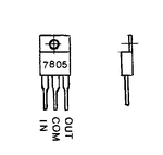
 

ha ha .. how can i or someone guess the transistor it may be MOSFET, BJT,THYRISTOR, JFET , REGULATOR. ETC.

you must post photos of the circuit diagrams and its input output connection to drill so after realizing purpose of your circuit i can suggest you alternate.
 

probably there something like IRFZ 48 (N-MOS 60V/50А/190W/0.018 Оhm/1,5 USD)
 

My ohmmeter gives me infinity in all directions.The device looks like
When device like this damaged ohm meter can not read continuity due to open circuit.
Attached image is 7805,its 3pin regulator ic in T0220 figure.
This type of drill have almost 2 mode of speed low and high through selector switch.
Speed also depends upon push switch,if we press softly speed is low.
Most chances are damaged component is MOSFET or SCR.
Because it is dc volt operated machine.
I see in high speed drills(operated with mains ac volts),speed of armature is being controlled with triacs.
I also have 18v dc operated low speed drill. I hope i can see inside it.
 

I agree, '7805' means it's a 5-volt voltage regulator. Maybe a dollar for a new one.

Look carefully on the old parts, to make sure there whether there is a clear insulator (shaped to fit the component). If you find one then it must be installed between the new part and the heatsink, with thermal grease in between.
 

1) I have made a sketch showing the inside, but i think i cannot send it on the site, because it is bitmap.If i cannot send the picture, i will try to describe.
2) When i press the switch, there is a working led who works
3) The picture i have shown was to give an idea of he shape of the component, there is no 7805 written on it.

- - - Updated - - -

mastercraft2.jpg I think i cannot open the plastic box, there is no screws.
 

now its ok
first disconnect the motor wires from switch and operate directly with battery in seris with a ammeter - if motor ampere is less than equal to 1.5 than u can use below circuit

use LM317 CIRCUIT TO OPERATE MOTOR WITH VARIABLE SPEED
**broken link removed**
it is an adjustable voltage regultor u can adjust volt by varying the 4.7k potentiometer

remember the pinout do not mistake.
https://4.bp.blogspot.com/-LhiYdu_H0Lw/TqDdhxxNSZI/AAAAAAAAAjw/YE20_Z95tH0/s1600/LM317.jpg
 

Is it found from the picture i have sent with 7805 on it?
there is no specifications on the transistor, no letters,no numbers, nothing.
Unlikely there can be used something other than mosfet with low RDS in control scheme of cordless drill.
 

2) When i press the switch, there is a working led who works
My guess is,blue and orange wires are in series of motor and battery terminal.
And black wire is for controlling speed through component.
Simply connect blue and orange wires with each other,and then press switch for a while to test motor is working or not.
I think motor should run with its max speed.
 

1) I have found that there is continuity betwen the middle wire of the transistor and the metallic plate.I wonder if this can help to establish wich one is collector, base or emitter.
2) As soon as possible, i will measure the voltages at these wires. I would prefer test the motor from these points, because battery wires or poles are not easy to access.
3) On a seller forum, about this item, one has asked for the "battery AH"? The answer was 1.3. I wonder if AH means ampers. I have posted on this forum too, for the transistor specifications.
4) The battery has three poles, A,B, on one side and C on the other. I have measured : Vab=0, Vac=9, Vbc=18.
 

1)
4) The battery has three poles, A,B, on one side and C on the other. I have measured : Vab=0, Vac=9, Vbc=18.
1) I have made new measures and now Vac=18
2) With switch on, voltage(orange/blue)=18 v, voltage(blue/black)=15 v
3) With switch off, no voltage.
4) Should i remove the motor wires at the switchbox or at the motor frame? (very hard to remove at the motor)
5) The owner manual says that the motor must run at 18 v.
 

Simply connect blue and orange wires with each other,and then press switch for a while to test motor is working or not.
I think motor should run with its max speed.

No it doesn't work; only the lead works. I will test the battery.


Status
Not open for further replies.

Part and Inventory Search

Welcome to EDABoard.com

Sponsor

Back
Top