Shreyas19
Newbie

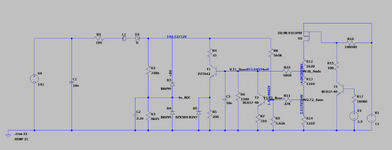
We are using this Circuit for the Input load circuit. This circuit will work for the input voltage range from 24 to 143 volt input voltage. For 24v typical value(25 degree) collector current from the PZTA42 transistor is 10mA as per simulation and for 143 input volt we observed that the hfe of the BC817-40 transistor according the datasheet for typical value is 400 but in the simulation we observed that for 143v typical value for the BC817-40 transistor's hfe in simulation is 122 for that we are getting 1.28mA Collector current and we get this or we calculate hfe for BC817-40 Transistor from simulation by using IC/IB Formula. So why there is change in hfe in simulation where actual we want 400 hfe but we are getting 122 ? To do worst case calculations we have used nodal analysis for this but we are failing because hfe is getting changed for BC817 transistor ? Is there any method to accurately calculate load current of this circuit ? Because in simulation we are getting proper results but we stuck at calculations.

