codemaster11
Full Member level 2

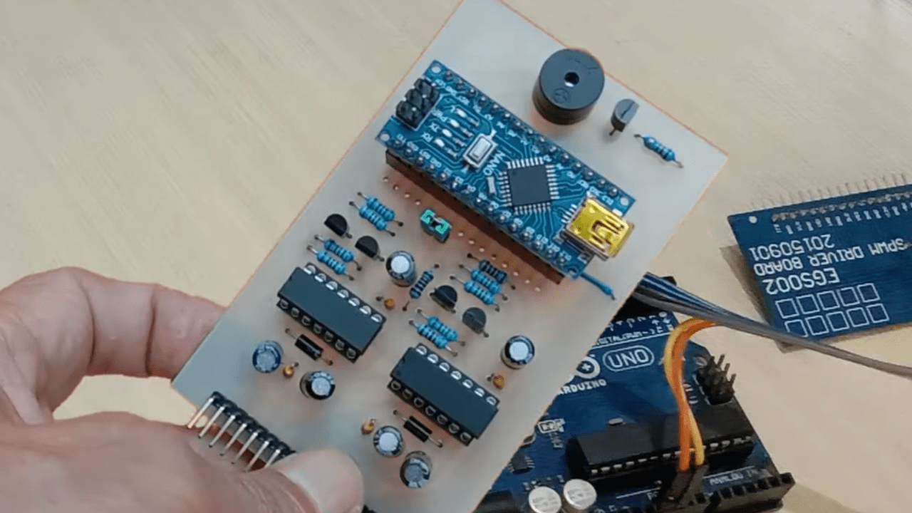
here is schematic diagram. arduino uno Pin9, 10 is for 10khz spwm frequency while pin 11, 12 for fundamental 50hz frequency.
below is a code i'm trying with dc to ac full bridge transformer less inverter with TLP250 instead IR2110. on real hardware it is
showing loading effect without real load with series light trick. study the code a little but didn't diagnose where the problem comes from. below is arduino code for atmega328p. any help will be appreciated. here is the code.
Code:
#include <avr/io.h>
#include <avr/interrupt.h>

/*
   SPWM_Nano_VFB3.ino

   Created : 8/11/2021
   Author  : yopie DIY

   Left bridge used for fundamental signal (50Hz/60Hz), Right bridge for SPWM (10kHz carrier freq.)
   Sampling per Cycle
   ---> 10kHz/50Hz = 200
   ---> 10kHZ/60hz = 166
   Look Up table entries use only half cycles (identical positive and negative cycles)
   50 Hz --->  200/2 = 100 entries
   60 Hz --->  167/2 = 83 entries

   SPWM clock = fXTAL/freq. carrier = 16.000.000/10.000 = 1.600 clock.
   WGM mode 8 is used, so ICR1 = 1.600/2 = 800 clk
   Look up tables for a half cycle (100 or 83 entries), max value = 800 (100% duty cycle)is loaded into register ICR1.

  This code is for 50Hz !!!
  for 60Hz use the Lookup Table for 60Hz and use the code marked on the ISR(TIMER1_OVF_vect) !!!
*/

const byte      vfbPin = A0,
                tfbPin = A1,
                battPin = A2;
volatile double percentMod;
int             phs;

//---------------------------------Look Up Table for 50 Hz---------------------------------------
int lookUp1[] = {
  0,  25, 50, 75, 100, 125, 150, 175, 199, 223, 247, 271, 294, 318, 341, 363, 385, 407, 429, 450,
  470, 490, 510, 529, 548, 566, 583, 600, 616, 632, 647, 662, 675, 689, 701, 713, 724, 734, 744, 753,
  761, 768, 775, 781, 786, 790, 794, 796, 798, 800, 800, 800, 798, 796, 794, 790, 786, 781, 775, 768,
  761, 753, 744, 734, 724, 713, 701, 689, 675, 662, 647, 632, 616, 600, 583, 566, 548, 529, 510, 490,
  470, 450, 429, 407, 385, 363, 341, 318, 294, 271, 247, 223, 199, 175, 150, 125, 100, 75, 50, 25, 0
};


/*
//---------------------------------Look Up Table for 60 Hz---------------------------------------
int lookUp1[] = {
  0, 30, 60, 90, 120, 150, 179, 208, 237, 266, 294, 322, 349, 376, 402, 428, 453, 478, 501, 524,
  547, 568, 589, 609, 628, 646, 664, 680, 695, 710, 723, 735, 747, 757, 766, 774, 781, 787, 792, 796,
  798, 800, 800, 799, 797, 794, 790, 784, 778, 770, 762, 752, 741, 729, 717, 703, 688, 672, 655, 637,
  619, 599, 579, 558, 536, 513, 489, 465, 441, 415, 389, 363, 335, 308, 280, 252, 223, 194, 164, 135,
  105, 75, 45, 15, 0};
*/


void setup() {
  // Register initilisation, see datasheet for more detail.
  TCCR1A = 0b10110000;
  /*      10xxxxxx Clear OC1A/OC1B on compare match when up-counting. Set OC1A/OC1B on compare match when down counting
          xx11xxxx Set OC1A/OC1B on compare match when up-counting. Clear OC1A/OC1B on compare match when down counting.
          xxxxxx00 WGM1 1:0 for waveform 8 (phase freq. correct).
  */
  TCCR1B = 0b00010001;
  /*      000xxxxx
          xxx10xxx WGM1 3:2 for waveform mode 8.
          xxxxx001 no prescale on the counter.
  */
  TIMSK1 = 0b00000001;
  /*      xxxxxxx1 TOV1 Flag interrupt enable. */
  ICR1   = 800;      /* Counter TOP value (at 16MHz XTAL, SPWM carrier freq. 10kHz, 200 samples/cycle).*/
  sei();             /* Enable global interrupts.*/
  DDRB = 0b00011110; /* Pin 9, 10, 11, 12 as outputs.*/
  PORTB = 0;

  pinMode(13, OUTPUT);
  pinMode(8, OUTPUT);
  pinMode(7, OUTPUT);
  pinMode(2, INPUT_PULLUP);

  percentMod = 0.01;
  for (int i = 0; i < 75; i++) {              // Soft Start
    percentMod = percentMod + 0.01;
    delay(20);
  }
}


void alarmIndication(int alarm)
{
  TCCR1A = 0;                             // shutdown SPWM output
  TIMSK1 = 0;
  PORTB &= 0b11100001;
loopX:
  for (int i = 0; i < alarm; i++) {
    digitalWrite(7, HIGH);                // turn ON LED and Buzzer
    digitalWrite(13, HIGH);
    delay(200);
    digitalWrite(7, LOW);                 // then turn OFF
    digitalWrite(13, LOW);
    delay(200);
  }
  delay(1000);
  goto loopX;                           //never ending story... until reset
}

void feedBackTest(float vfbIn, int tfbIn, int battIn) {
  long alrm;
  static int alrmCnt;

  if (digitalRead(2) == LOW) return;
  if (phs != 1) return;

  alrm = constrain(vfbIn, 462, 660);
  if (alrm !=vfbIn) alrmCnt++; else alrmCnt=0;
  if (alrm == 462 && alrmCnt >= 150) alarmIndication(2);        // underVoltage @ 2.5V --> 2.75 / 5 x 1023 = 562
  if (alrm == 660 && alrmCnt >=15) alarmIndication(3);          // overVoltage @ 3.15V --> 3.15 / 5 x 1023 = 645
  if (tfbIn >= 924) alarmIndication(4);                         // over temp @ 80C --> 10k/(10k + 1.068k) x 1023 =924
  if (battIn <= 457) alarmIndication(5);                        // low batt @ 10.5V --> (2k7/12.7k x 10.5) / 5 x 1023 = 457
  if (tfbIn >= 725 && digitalRead(8) == LOW)  digitalWrite(8, HIGH);  // fan ON @45C --> 725
  if (tfbIn <= 679 && digitalRead(8) == HIGH) digitalWrite(8, LOW);   // fan OFF @40C --> 679

}

void loop() {
  static int vfbValue;
  static int vfbValue1;
  static int vfbRise = 0;
  static float vMax;
  float alrm = 0;
  static int alrmCnt = 0;
  float ampDiff;

  if (phs = 1) {
    vfbValue1 = vfbValue;
    vfbValue = analogRead(vfbPin);                              // vfbPin = 0 to 5V ---> vfbValue = 0 to 1023

    if (vfbValue > vfbValue1 && vfbValue > 200) vfbRise = 1;     //check for positif cycle, bigger than noise
     if (vfbValue < vfbValue1 && vfbRise == 1) {                 // maximum vfb value reached
      vfbRise = 0;
      vMax = vfbValue1;
      ampDiff = 614 - vMax;
      if (ampDiff > 5 || ampDiff < -5) {
        percentMod = percentMod + (ampDiff / vMax);               // voltage correction
        if (percentMod > 0.97) percentMod = 0.97;               // limit duty cycle to 97%
      }

     feedBackTest(vMax, analogRead(tfbPin), analogRead(battPin));
      vMax = 0;
    }
  }
}


/*---------------------------------------------------------------------------------------------------------*/
ISR(TIMER1_OVF_vect) {
  static int num;
  static int  ph;
  static int dtA = 0;
  static int dtB = 5;

  if (num >= 99) {    // <------------------ 50 Hz !!!
//  if (num >= 82) {    // <------------------ 60 Hz !!!
    if (ph == 0) {         // OC1A as SPWM out
      TCCR1A = 0b10110000; // clear OC1A, set OC1B on compare match
      dtA = 0;             // no dead time
      dtB = 5;            // adding dead time to OC1B
    } else {
      TCCR1A = 0b11100000; // OC1B as SPWM out
      dtA = 5;
      dtB = 0;
    }
    ph ^= 1;
  }
  OCR1A = int(lookUp1[num] * percentMod) + dtA; // SPWM width update
  OCR1B = int(lookUp1[num] * percentMod) + dtB; // note: 0.7 used to reduce inveter output voltage

  num++;
  if (num >= 100) {                   // toggle left bridge (50Hz) !!!
//  if (num >= 83) {                   // toggle left bridge (60Hz) !!!
    delayMicroseconds(60);
    if (ph == 1) {
      digitalWrite(12, LOW);
      digitalWrite(11, HIGH);
      phs = 1;
    } else {
      digitalWrite(11, LOW);
      digitalWrite(12, HIGH);
      phs = 0;
    }
    num = 0;
  }
}
Last edited by a moderator: