Continue to Site

Welcome to EDAboard.com

Welcome to our site! EDAboard.com is an international Electronics Discussion Forum focused on EDA software, circuits, schematics, books, theory, papers, asic, pld, 8051, DSP, Network, RF, Analog Design, PCB, Service Manuals... and a whole lot more! To participate you need to register. Registration is free. Click here to register now.

Total power dissipation of a circuit in Ltspice

Status
Not open for further replies.

Ikh1

Newbie
Newbie level 4
Joined
Nov 23, 2021
Messages
5
Helped
0
Reputation
0
Reaction score
0
Trophy points
1
Activity points
33
Hello, I have a circuit with 40+ components and multiple voltage sources. How can I calculate the total power dissipation in Ltspice? I know how to find the dissipation for individual components but is there a way to calculate it at once for the whole CMOS circuit like in pspice. Also, is there a way to get it in text instead of the waveform?
 

Hi,

not sure how your circuit looks like:

but I guess there is an (or more) electrical input and an (or more) electrical outputs.

then
power_dissipation = input_power - output_power

Klaus
 

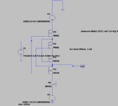
Please can you tell if it applies to this circuit as well?
1637690450422.png
 

Hi,

I see no reason why it should not.

For exact calculation you have to take the pulse input also into account.

M5_gate seems to not be connected properly.

Klaus
 

    Ikh1

    Points: 2
    Helpful Answer Positive Rating
Thank you, fixed the M5_gate. I'm confused about how to find the output power.
The input power components would be 2 sine sources as well as pulse input. But what about the output?
 

Hi,

generally:
P = V x I

for non DC signals you should calculatate the average of P over a useful time. (at least one fullwave)

Independent of: input, output, waveform, frequency, phase shift, overtones, non linearty, ....

Klaus
 

I often use efficiency report.
Open simulation command, tick []
1638000398776.png

Then open View menu on Taskbar, click []
1638000458064.png

Result will appear like this:
1638000560579.png
 

You should mention that the option "Stop simulating if steady state is detected" depends on a special function, which is built into most LT SMPS controller models. As stated in the online help under Circuit Efficiency Calculation
The program will detect the steady state by checking the internal state of the switcher macromodel. It doesn't work when a switching regulator part is not part of the circuit because the steady state detection is implemented in the model -- usually by looking for the the current flowing out of the error amplifier to drop to zero as integrated over a switching cycle.

You can also implement steady state detection by using the EAclk parameter of the OTA special function.
 

You should mention that the option "Stop simulating if steady state is detected" depends on a special function, which is built into most LT SMPS controller models. As stated in the online help under Circuit Efficiency Calculation


You can also implement steady state detection by using the EAclk parameter of the OTA special function.
Yes, sometime it will not stop until the end of simulation time.
If "stop" by hand, the result will not accurate. But acceptable.
 

I get the 'Don't know how to detect this circuit's steady state' message on trying this.
Yes, the circuit is too simple and don't have define state.
Other way is use semi-hand.
Use .meas macro. Define all net/trace name and place formula in Spice directive.
The result will appear in Log file (Ctrl + L).
It is trouble for many component.

Example:
1639416284210.png
 

Status
Not open for further replies.

Part and Inventory Search

Welcome to EDABoard.com

Sponsor

Back
Top