newbiebuntu
Newbie level 6

I would like to build an on/off switch for a science project. I am new to boards and electronics but have an interesting idea.
I'm looking for the switch to turn on when a ohm rating above 40 gets sent through a ground wire. It would then be off with any ohm rating from 0-39 (+/- 5 or 10 ohms is okay).
0-39 Ohms = good
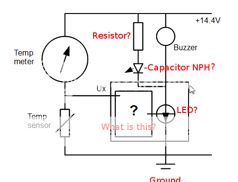
40+ ohms = bad and the negative after the switch is turned on and a current is allowed through to turn on an LED light which is always plugged into positive. A piezo buzzer for an audible alarm could be added along with the LED.
Such an ohm reading would be read from a thermal sending unit (thermistor) to a gauge showing how cold or hot something is based on the ohm rating received from the thermal sending unit. Fridges, cars, etc have these setups for their gauges.
Thank you for your time and effort. I'm not sure if I was clear enough or not, and if I did anything wrong by posting this here. Again I'm a complete beginner and hope to get some info and use this as a starting point.
I read somewhere yesterday here someone was using a transistor as a switch?
Update: I'll be using a car battery to power everything. Working on the blinking LED, I take Supply Voltage minus LED Voltage divided by LED current. So in my case (14.4V battery - 3.0V LED) / .035A which is 35mAmps max = 325ohms, rounded up to next highest value of 330ohms (I'm using a 1/2W resistor).
I'm looking for the switch to turn on when a ohm rating above 40 gets sent through a ground wire. It would then be off with any ohm rating from 0-39 (+/- 5 or 10 ohms is okay).
0-39 Ohms = good
40+ ohms = bad and the negative after the switch is turned on and a current is allowed through to turn on an LED light which is always plugged into positive. A piezo buzzer for an audible alarm could be added along with the LED.
Such an ohm reading would be read from a thermal sending unit (thermistor) to a gauge showing how cold or hot something is based on the ohm rating received from the thermal sending unit. Fridges, cars, etc have these setups for their gauges.
Thank you for your time and effort. I'm not sure if I was clear enough or not, and if I did anything wrong by posting this here. Again I'm a complete beginner and hope to get some info and use this as a starting point.
I read somewhere yesterday here someone was using a transistor as a switch?
Update: I'll be using a car battery to power everything. Working on the blinking LED, I take Supply Voltage minus LED Voltage divided by LED current. So in my case (14.4V battery - 3.0V LED) / .035A which is 35mAmps max = 325ohms, rounded up to next highest value of 330ohms (I'm using a 1/2W resistor).
Last edited:


")