Continue to Site

Welcome to EDAboard.com

Welcome to our site! EDAboard.com is an international Electronics Discussion Forum focused on EDA software, circuits, schematics, books, theory, papers, asic, pld, 8051, DSP, Network, RF, Analog Design, PCB, Service Manuals... and a whole lot more! To participate you need to register. Registration is free. Click here to register now.

TL494 pwm ic , Current sensing.

jatin12345

Newbie level 5
Newbie level 5
Joined
Jan 16, 2011
Messages
9
Helped
0
Reputation
0
Reaction score
0
Trophy points
1,281
Activity points
1,350
Dear Friends ,

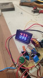
I am using tl494 to design a dc to dc BOOST converter :
I/P : 12V DC.
O/P: 12 TO 60V DC.(adjustable).

I need to apply current sensing resistor to read o/p current.
I am sharing a circuit which i am using.

Using 100uh toroidal inductor as L2.
I am using 0.1E 5W resistor instead of Two 0.22E resistors shown in the circuit.
I have set current limit as 0.5V (5A x 0.1R) = 0.5V to limit the current exceeding above 5A at pin 15.

The mosfet is Heating up in my circuit even without load connected.

Is the current sensing resistor correctly placed or it has to be placed at o/p terminal between x2-1 and ground?


TL494 CKT.jpg
 
Last edited:
The boost converter needs a load attached at all times it operates. Each cycle has the inductor sending a burst of current to the output stage. Possibly your resistor network serves as a bleeder load and holds the output voltage down to a manageable level. However if it's only a slight load it might allow the output voltage to reach damaging levels.
 
you haven't got a proper error amp circuit set up to limit the slew rate and freq response of the comp pin - you need a slower volt loop controller as the boost has an right hand plane zero - which gives the power stage extra delay, lowering gain but also giving phase lag.

research control loops for boost converters - it pays to have an over voltage stop circuit as well in case the feedback loop fails

the current limit ckt might need inverting to fit in with the logic of the TL494
 
I have made some changes in the circuit.as shown below.
1.jpg


Using approx 50 ohm resistor 10W in output as load.
using 0.1 Ohm , 5w resistor instead of R6 AND R7 for current sensing.

Sharing the scope waveform for
1. TL494 pin (8-11(shorted) to mosfet gate pin 1) in yellow.
2. Mosfet Drain switching on off pulse in blue(mosfet pin 2).
2.jpg


1. I have fixed voltage at the pin 2 of tl494 as 2.5V.
2. Fixed voltage at pin15 of TL494 as 0.5V(assuming max current flow at the load resistor to be 5A . i.e V=IR i.e V = 5Amp x 0.1Ohm = 0.5V.

My concern is that How do i increase the voltage at the output which is still showing only 12.6 V dc.(Not shown in the scope ).
 
if you turn the pot down ( pot 1 ) and the Vout don't go up - then the current limit must be limiting Vout for fixed load and fixed Imax.
--- Updated ---

without proper feedback, though, ( which is essentially a modified low pass filter around the error amps ) you'll never have effective control.
--- Updated ---

have you inverted your pwm by the C & E connections ?
 
Last edited:
Currently I am able to get :
1. No load voltage : up to 60V.
2. On connecting resistive load of 48ohm resistor at 60V output:
I expect Current flowing in load resistor : V/R = 60 V / 48 ohm = 1.25A.Therefore current sensing resistor (0.1 ohm will give 0.125V) across it.

I have set current limit at 500mv at pin 15. Current sensing is showing 0.125V or 125 mv at pin 16. I believe it should be able to work as the current is within limit.
But the moment i connect the resistive load of 48 ohm . The output voltage shows 12V instead of 60V.I think the switching operation stops on connecting load.
what could be the reason for this .

without load :
4.jpg


With load of resistors the output changes to :

3.jpg
 
Sharing scope waveform for:


1. No load condition:
5.jpg


2. Load connected 48Ohm resistor.

6.jpg


Yellow is the gate drive .
Blue is the voltage at Drain of mosfet IRFZ44N.

What could be the reason of Converter switching failure at load resistor connection.
 
You need to read the full data sheet for the 494 which shows a feedback loop in one of the diagrams
Hello , can you please elaborate what problem do you see in schematic relating to the scope waveforms shown. I want to know what is wrong with the feed back loop.
I am using R13 as 510 ohm and R15 as 51k therefore gain (1+ Rf / Ri) = 101 as specified by datasheet.
attaching current updated circuit as shown below:

7.jpg
 

LaTeX Commands Quick-Menu:

Similar threads

Part and Inventory Search

Welcome to EDABoard.com

Sponsor

Back
Top