Continue to Site

Welcome to EDAboard.com

Welcome to our site! EDAboard.com is an international Electronics Discussion Forum focused on EDA software, circuits, schematics, books, theory, papers, asic, pld, 8051, DSP, Network, RF, Analog Design, PCB, Service Manuals... and a whole lot more! To participate you need to register. Registration is free. Click here to register now.

TL431 + LM317 + PNP = confuzion

Status
Not open for further replies.

Xymox

Newbie level 5
Newbie level 5
Joined
Jun 11, 2022
Messages
9
Helped
0
Reputation
0
Reaction score
0
Trophy points
1
Activity points
103
OK I am now confuzed... I have run across a linear power supply with a circuit I am having trouble understanding.. With no load it has the TL431 sawtooth instability and about 100mV of it. With any load above about 75mA it changes to a zener like wideband random noise of about 3mV pk-pk and this noise does not vary with load. This odd behavior caused me to look at the circuit..

Why the high values for the TL431 adj side ? Does this give the TL431 gain ? Why ?

WHy is there a LIM317 hooked to the PNP ? WHy not just drive a darlington output and skip the LM 317. Is the 317 a 2nd stage of regulation and can then drive a std PNP ? Note the PNP is kinda a odd choice of part.

WHY do this design ? See schematic..
 

Attachments

  • LinReg3.gif
    LinReg3.gif
    60.2 KB · Views: 313

LM317 out has no controlled sinking capability, it can't drive the PNP, respectively the schematic makes no sense. Particularly there's no feedback path from the output, why do you think it's a linear regular?
 

Exactly...

I do not understand this device. I am asking here because its really strange. *Supposedly* the mfgr used SPICE tools and models for the parts and found a unusual implementation. Or is BS..

WHy would they make something like this, when it would be cheaper and more regulated to do something more sane tho ?

I refer to the term "linear" as a name VS what it implies :) hehehe..

Its a very odd circuit. It does work. They are hot sellers. It does seem to hold regulation, sorta, as you would expect from no feedback. Of course it selling means nothing.. Maybe feedback has some downside ? Transit response times ? I dont know.. Its really odd.. A TL431 is really odd. One of the datasheets on ON semi shows a application as a phono preamplifer that drives a speaker, with just a TL431 as the active part. Its a odd one, from another era.

The seller makes a lot of supplies.

This supply is selling well. They seem to sell about 40 a week resetting this when it gets to 0 twice a week.

The TL431 has a really high resistivity divider. This is odd. Thats 70K. I can't find any use of the TL431 with values like that. It can be operated nearly open loop with gain.

I have been trying to break this down section by section and trying to wrap my brain around it. I am still in trouble..

I have a thread going here with more discussion.

Strange behavior.

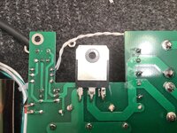
Here it is physically..
 

Attachments

  • IMG_6207.jpg
    IMG_6207.jpg
    2.5 MB · Views: 136
  • IMG_6221.jpg
    IMG_6221.jpg
    2.4 MB · Views: 114

i agree. This circuit makes zero sense.

The LM317 can’t drive the PNP.

Where did you find this circuit? Have you tried simulating it.?
 

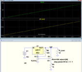
Below is the LTspice simulation of a circuit properly using a TL431 to provide a very stable output voltage using an LM317.
It has the advantage that remote sensing from both the output and the ground connections can be used, unlike an LM317 by itself, which can only remove sense the ground.

1655046642721.png
 

i agree. This circuit makes zero sense.

The LM317 can’t drive the PNP.

Where did you find this circuit? Have you tried simulating it.?

I bought the linear supply listed above and discovered this weird circuit inside.

I am not smart enough and dont have the tools to simulate it.

Its does mostly work, but has the weird behavior I show in the above vid. Its popular and sellling.
 

Below is the LTspice simulation of a circuit properly using a TL431 to provide a very stable output voltage using an LM317.
It has the advantage that remote sensing from both the output and the ground connections can be used, unlike an LM317 by itself, which can only remove sense the ground.

View attachment 176797

Yep. This is a well established topology and is what I THOUGHT was going on until I looked closer because of the weird instability ringing and high noise.

That 70K of restive divider is weird. Well,, the whole thing is weird. It really makes no sense to me at all.
 

I bought the linear supply listed above and discovered this weird circuit inside.

I am not smart enough and dont have the tools to simulate it.

Its does mostly work, but has the weird behavior I show in the above vid. Its popular and sellling.
Simulators, e.g. LTspice, are free.
 

Simulators, e.g. LTspice, are free.
But they take experence to use.,. And in this case the model for the TL431 looks tricky to get right..

I was hoping there might be a really experenced SPICE user here maybe with TL431 experence and power supply experence who could sort this out and maybe help me in the right direction.

Honestly, I am good with the device. Strangely its working better for a use I have better then a Lambda LCS-A15 which I recapped and put in a better Vref.. I get 15uV pk-pk noise and +-0.0001Vdc drift with awesome transit response and really low impeadance across a widebandwidth... I DO NOT understand why this $100 ebay linear is working better for my use. That was why I dug into it and discovered this weird circuit. Well, I dug into the circuit to add sensing..

I am good with the supply. Its just really odd and I would like to understand it better. So far no one has been able to answer even the basic question of why use a 10k > 50k > 10k on the adj of the TL431. This is gain right ? Why would you operate a TL431 with gain in a Vreg circuit ? I think the LM317 + PNP is obvious - higher current and lower output impeadance ? But why not just use a power FET or something, why use a LM317 + NJW0302. Why no neg feedback ? It seems like someone either had ZERO idea what they were doing, made a mistake OR maybe they came up with something interesting..

What would happen if I moved that + and - sides of the resistor divider out past the 317 and PNP ? So sensed things out there ? I assume it would self distruct in a fiery burst of ringing..
 

the main o/p xtor should be an NPN, not pnp, with b-e resistor as shown - on the new b-e positions
But this is what is in the circuit ? I am trying to understand what is already working.
 

Attachments

  • IMG_6207.jpg
    IMG_6207.jpg
    2.5 MB · Views: 105
  • IMG_6221.jpg
    IMG_6221.jpg
    2.4 MB · Views: 111

But they take experence to use.,.
did you try it on your own? It´s not as difficult as one might think. to get used to it.
Give it a try, but start with simple things, like an R-C ...

and difficult "to use" or " to interprete the results"?

I was hoping there might be a really experenced SPICE user here
I fully understand that.
And if you are lucky you find someone.
But that´s not the idea of a forum. "helping" does not mean others do your job, but others explain how to do it .. and point to mistakes. So in best case the next time you can do it on your own. A gain for the future.

Klaus
or the circuit has not been copied exactly from the actual hardware ....
in the photo:
* PNP_pin1 (base) goes to LM317_pin3 (input)

but in the schematic:
* PNP_base goes to LM317_OUT

or am I mistaken?
 

did you try it on your own? It´s not as difficult as one might think. to get used to it.
Give it a try, but start with simple things, like an R-C ...

and difficult "to use" or " to interprete the results"?


I fully understand that.
And if you are lucky you find someone.
But that´s not the idea of a forum. "helping" does not mean others do your job, but others explain how to do it .. and point to mistakes. So in best case the next time you can do it on your own. A gain for the future.

Klaus

in the photo:
* PNP_pin1 (base) goes to LM317_pin3 (input)

but in the schematic:
* PNP_base goes to LM317_OUT

or am I mistaken?
100% correct....

i have redone the schematic... This makes way more sense.. i *think* this is correct...
 

Attachments

  • LinearX.gif
    LinearX.gif
    120.4 KB · Views: 184

That makes MUCH more sense, it uses the transistor as a 'wrap around' current booster for the LM317 and the output voltage is sensed to regulate the voltage.

Brian.
 

Um, will that ckt work ... (?) - I have a few concerns ....
--- Updated ---

this from the data sheet:
1655110256631.png

--- Updated ---

and for completeness ( min load etc ) :
1655110848757.png
 
Last edited:

Status
Not open for further replies.

Similar threads

Part and Inventory Search

Welcome to EDABoard.com

Sponsor

Back
Top