d123
Advanced Member level 5

- Joined
- Jun 7, 2015
- Messages
- 2,505
- Helped
- 494
- Reputation
- 992
- Reaction score
- 525
- Trophy points
- 1,393
- Location
- Spain
- Activity points
- 27,148
Hi,
I found this method of generating a negative voltage reference from a TL431:
**broken link removed**

It works, both as a -2.49V reference or as whatever you like with a divider, e.g. -5V out.
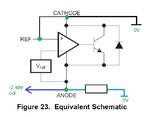
I tried to understand the detailed schematic, and the functional diagram, and do not understand how this works, as a few NPNs that when used normally as a positive reference now seem to be receiving a low signal, and I'm wondering why there are a few transistors receiving what looks to an untrained eye as 0V power supply. I am not versed in understanding Op Amp architectures at all, so don't really understand the positive use either, but can get some idea of what will be powered and "on" or "off".
Two questions please:
Is it okay to do this or is it Not Recommended for Any Designs?
How does the internal OpAmp still work? is it because the V+ and V- pins still see a difference in potential and the polarity doesn't matter?


Thanks.
- - - Updated - - -
...This makes me wonder if a dual supply Op Amp that never needs the output to swing above 0V could be powered from 0V and -5V (rather than, for example, +2.5V and -2.5V), because all the IC sees/requires is sufficient difference in potential between its power rails to function correctly. Is that so?
I found this method of generating a negative voltage reference from a TL431:
**broken link removed**

It works, both as a -2.49V reference or as whatever you like with a divider, e.g. -5V out.
I tried to understand the detailed schematic, and the functional diagram, and do not understand how this works, as a few NPNs that when used normally as a positive reference now seem to be receiving a low signal, and I'm wondering why there are a few transistors receiving what looks to an untrained eye as 0V power supply. I am not versed in understanding Op Amp architectures at all, so don't really understand the positive use either, but can get some idea of what will be powered and "on" or "off".
Two questions please:
Is it okay to do this or is it Not Recommended for Any Designs?
How does the internal OpAmp still work? is it because the V+ and V- pins still see a difference in potential and the polarity doesn't matter?


Thanks.
- - - Updated - - -
...This makes me wonder if a dual supply Op Amp that never needs the output to swing above 0V could be powered from 0V and -5V (rather than, for example, +2.5V and -2.5V), because all the IC sees/requires is sufficient difference in potential between its power rails to function correctly. Is that so?


