Vermes
Advanced Member level 4

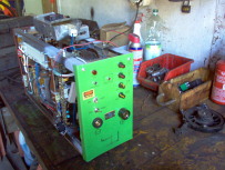
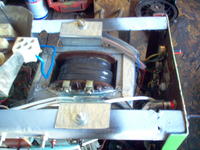
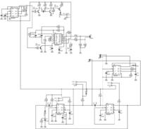
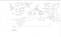
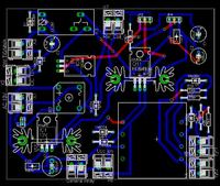
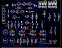
Main assumption of this project was to improve a simple transformer welder (primary winding - wire 1x2mm, secondary winding – copper tape 3x9mm, diameter of core: 8cm x 7cm) by adding a rectifier. Welding should be done using DC. The device should be also equipped with adjustable current by controlling the angle of thyristors drive. The welder operates on pulse current.
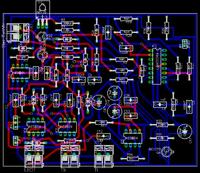
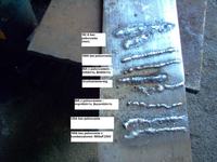
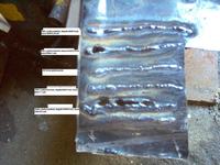
The frequency of charging the inverter voltage multiplier (from 400V to 800V) was increased from initial 20kHz to 50kHz. Three resistors 1,2k/10w are connected in parallel and a toroidal mini-choke calm the operation of the inverter's transformer (400V/50kHz) and you do not have to use much of them (3 pieces per branch = total 6 pieces, but as well you can use only 2 pieces per branch or even only a single one). The welder (its driver) ensures really precise current adjustment. Samples of plates were made using electrodes 2,0mm ER146 and ER246 on 1,0mm plate and electrodes 2,5mm on 2,0mm plate.
Ionizer provides quite reliable ignition of the arc at each current – even 30A. The choke was calculated and made for the following assumptions:
- max current = 100A
- maximum arc voltage drop (from 30V) Vs=10V
Parameters of the choke:
- cross-section surface of the core = 18cm2
- winding = 25mm2
- number of turns = 12
- gap = 0,1mm
Unfortunately, the inductance is too small, so you need to add a 1800uF/250V capacitor. Without it, even lighting the arc with working ionizer is harder than if you use it. The optimum is to use simultaneously a choke with 2 times greater inductance and a 2.000 – 10.000uF capacitor.
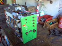
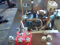
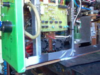
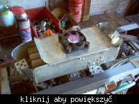
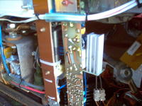
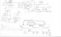
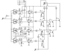
Pictures:
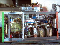
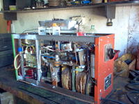
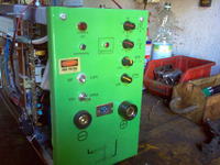

Link to original thread (useful attachment) – http://www.elektroda.pl/rtvforum/topic773495.html Zbudowałem spawarkę TIG DC (wersja PULS + HF) url
