Vermes
Advanced Member level 4

Parameters:
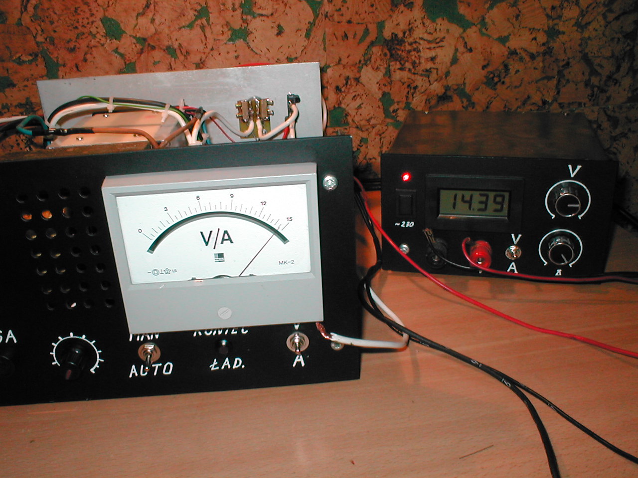
- voltage regulated 1-15V
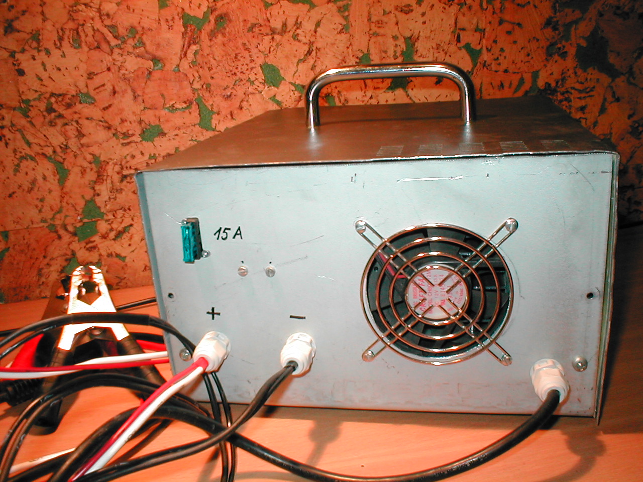
- current regulated to 8A
- protection against overcharging the accumulator 14,4V
- protection against accidental short circuit terminals
- polarity protection

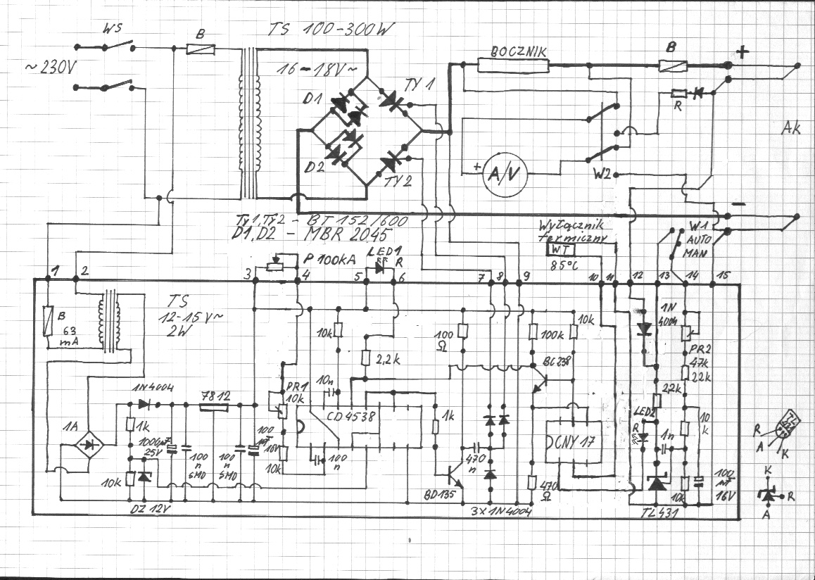
How it works:
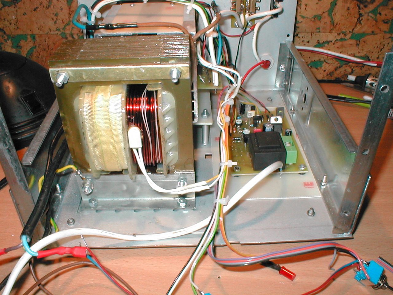
AC voltage from the transformer secondary winding of about 17V is fed to the controlled thyristor-diode bridge. Then, depending on the control pulses, it is fed to the accumulator terminals.
The driver consists of: the mains transformer of 2W and a voltage about 12V, voltage stabilizer LM7812, dual CD4538 multivibrator giving control pulses to the thyristor gates and the accumulator voltage control system consisting of CNY17 optocoupler and a reference voltage source circuit TL431 working as comparator.
If the voltage at the output R of the circuit TL431 is lower than 2,5V (circuit of the divider from PR2 with resistors), the current does not flow through TL431, but through LED2 and CNY17, blocking transistor BC288, giving high state at the resetting input 13 of CD4538 and normal operation (giving control pulses to the thyristor gates). If the voltage rises (due to charge the accumulator), TL431 becomes conductive, the current stops flowing through LED2 and CNY17, BC238 is actuated and low state given on input 13. Generating control pulses to the thyristor gates is stopped then and the voltage for the accumulator is cut off. Voltage of the cut off is set by PR2 to 14,4V, on the output.
While charging, LED1 diode lights up more often and almost constantly in the final stage. 2 temperature sensors 80 degrees Celsius were used. One of them is glued to the heat sink and the second to the secondary winding of the mains transformer. The sensors are connected in series. Activation of the sensor causes the optocoupler voltage cut-off, locking the multivibrator in CD4538 and a lack of control of the thyristor gates.
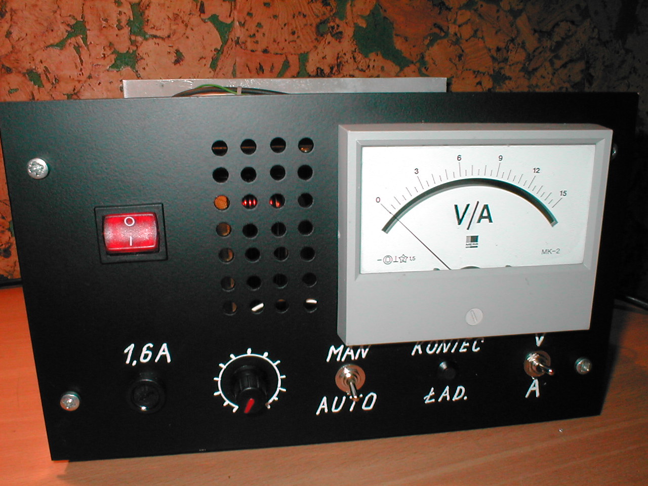
The ventilator is permanently connected to the voltage of the accumulator.
The system has a switch AUT/MAN. In MAN position, the accumulator voltage control system is switched off and the accumulator can be personally charged with control over the voltage.
Components:
- main transformer (security transformer 160W 24V with re-winded secondary winding to 17V)
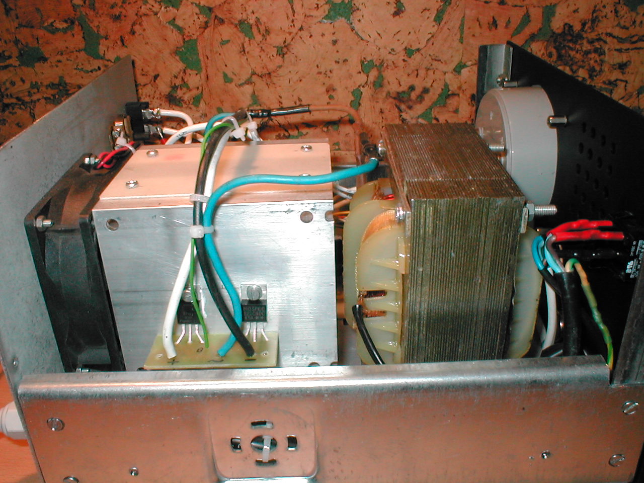
- thyristors BT152/600
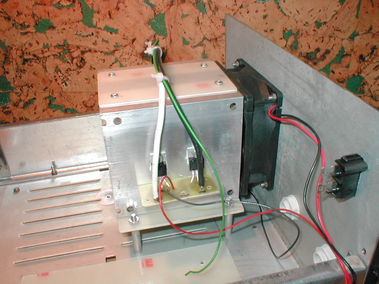
- diodes MBR 2045 and ventilator from computer power supply
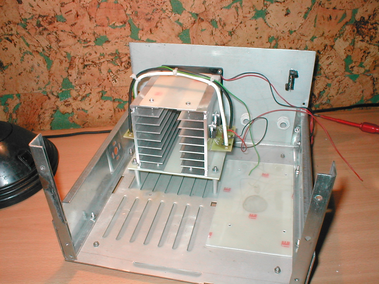
- heat sinks
- sensor
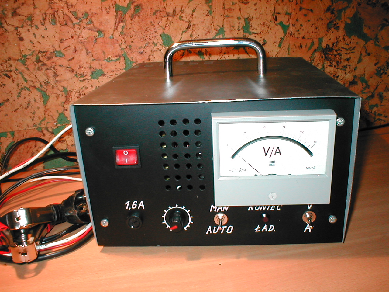
- housing
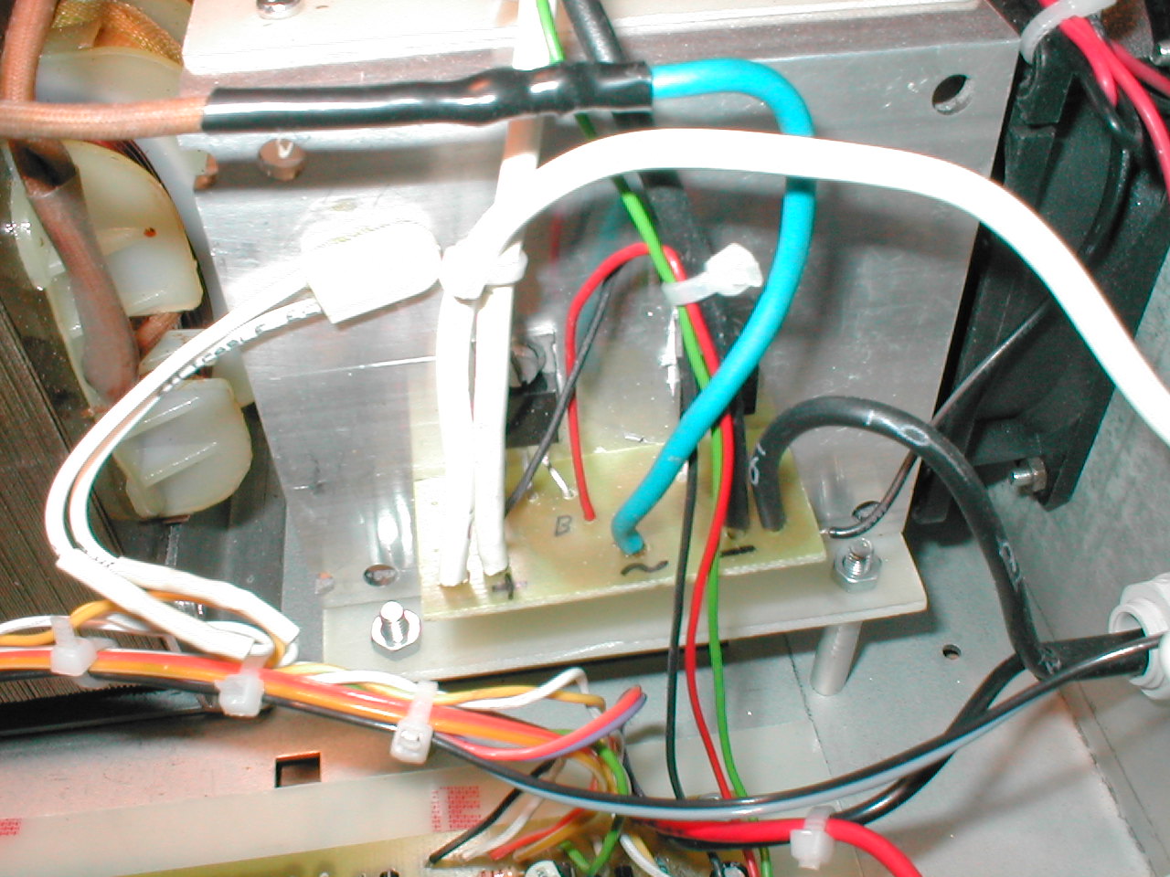
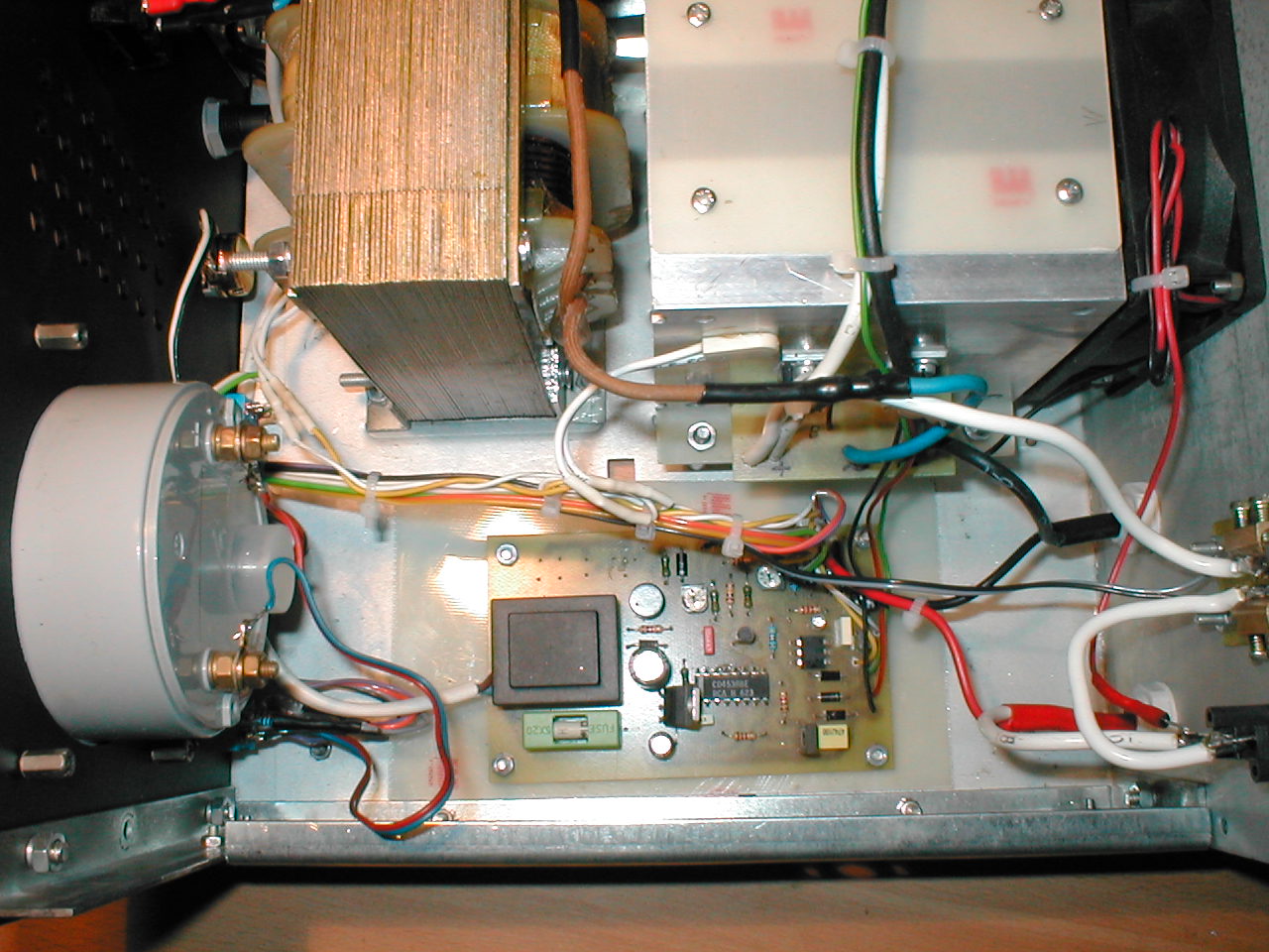
Photos:

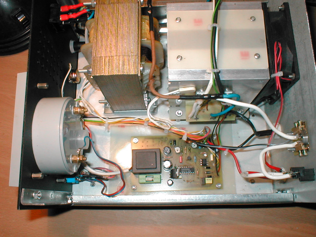
Notes:
Ammeter shunt is made of double thrust belt 4x0,5 KANTHAL.
Diode-thyristor bridge is placed on separate plates and can conduct to 20A. Heat sinks are isolated from each other and housing.
Transformer secondary winding is wounded around a wire with a diameter of about 2,2mm and with forced cooling it may produce approximately 8A, but a more powerful transformer can be mounted.
The printed board is manually painted with a board pen.
Charging:
The charging current 1/10 of full accumulator capacity, after the time, depending on the degree of discharge, LED1 starts flashing. The closer to the voltage of 14,4V, the more often the diode flashes. At the end of charging, the diode is lit almost all the time. A small hysteresis is introduced by electrolytic capacitor at the end of R TL431 circuit.
Link to original thread – Prostownik tyrystorowy do akumulatorów samochodowych
