Continue to Site

Welcome to EDAboard.com

Welcome to our site! EDAboard.com is an international Electronics Discussion Forum focused on EDA software, circuits, schematics, books, theory, papers, asic, pld, 8051, DSP, Network, RF, Analog Design, PCB, Service Manuals... and a whole lot more! To participate you need to register. Registration is free. Click here to register now.

Thyristor 230V Backup circuit

Status
Not open for further replies.

requester

Newbie level 6
Newbie level 6
Joined
Oct 7, 2012
Messages
12
Helped
0
Reputation
0
Reaction score
0
Trophy points
1,281
Activity points
1,384
Hi guys. Again some homework I can't seem to get my head around.

Design a circuit, including a thyristor, where a lamp of 6V fead by the electrical grid (via a transfo). The lamp should be kept burning when the grid power is removed. As backup, use a 9V battery.

My circuit is this:

backupsysteem.PNG


When I disconnect the 9V battery multisim does not want to simulate. (simulation error)

The circuit is supposed to work in 2 ways right? disconnect the net.... 9V gives power //// disconnecting the 9V battery lets the net power the lamp ??? right?

Anyway, I'm not sure about it all and not at all about the calculations in this exercise.


Anyone who thinks the calculations + working ciruit is a peace of cake?!

Thanks in advance!
 

Hi Requester
Can i change your circuit ? or just this one is in your interest ? ( i can help you in both methods ! mine circuit or your circuit ! )
Anyone who thinks the calculations + working ciruit is a peace of cake?!
Piece of cake ? ha ha ! how you can send a piece of cake if i improve your circuit ?! :grin:

Best Wishes
Goldsmith
 

Hi Requester
Can i change your circuit ? or just this one is in your interest ? ( i can help you in both methods ! mine circuit or your circuit ! )

Piece of cake ? ha ha ! how you can send a piece of cake if i improve your circuit ?! :grin:

Best Wishes
Goldsmith

Yes, please go ahaid! If you have a solution to our (class) problem, I would to love to hear it.

I'll think 'bout the piece of cake :wink::grin:
 

A guidance :
If i was in you situation , i would use a diode and an opto triac and then a triac ! ( if you need to drive a 230 volts lamp ) ( diode won't allow the battery be in circuit when you've main voltage .) when main voltage is failed then diode will be on and then battery will be in circuit and then an opto coupler will be on and then a lamp will be on ! an easy process ! and of course a fast process !

I'll think 'bout the piece of cake
Surely you should think and find a reasonable solution for this issue ! :grin:

Good luck
Goldsmith
 

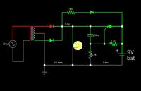
I'm trying your circuit in an animated simulator found at:

www.falstad.com/circuit

Here is a screenshot:


The shot is in mid-cycle.

I find that there is current flowing only through the bulb. Very little current flows through the other components.

I adjusted specs for the bulb to draw a few mA.

When I disconnect the 9V battery multisim does not want to simulate. (simulation error)

This simulator permits me to disconnect the battery.

As for when I disconnect grid power...

The battery powers the bulb slightly, however it is because current goes through the 2200 ohm resistor and gate of the scr. Current does not go through the scr proper.

----------------------------

Your circuit is a good try.

Configuring an scr circuit is not the easiest task. We must determine what polarity is correct for the gate drive? Where should ground be? Where should the load be?

I find that Falstad's animated simulator makes it easy to examine operation of circuits. To see for yourself, you might like to try your circuit in it. It's free.

To use an scr, it would help if you start with the simplest circuit and get the scr to power the lamp. Its gate needs to be referenced to the correct polarity. The load needs to be closest to the correct lead. Etc.

Then start adding the components that will provide backup power.

All this is to say, it's not an issue of getting the calculations right, at this point.
 

Can someone explain me why we trying to persuade 6V bulb to work on 9V ?

Final goal what you want to achieve is very simple and can be done with usage of only one diode. I dont see purpose of thyristor and other parts in this circuit, except rectifiers after transformer.
 
Last edited:

The problem with the circuit is that the bulb still uses power from the battery as well while the mains supply is present. No power must be consumed from the battery with the mains supply connected.
 

I guess, you should also be using a filter capacitor after rectification otherwise scr will coducting between rectified waves when voltage is low.
 

Another alternative is to use a small transistor to prevent the gate from firing when mains is present.
 

Attachments

  • light1.gif
    light1.gif
    9.8 KB · Views: 109

Status
Not open for further replies.

Similar threads

Part and Inventory Search

Welcome to EDABoard.com

Sponsor

Back
Top