Continue to Site

Welcome to EDAboard.com

Welcome to our site! EDAboard.com is an international Electronics Discussion Forum focused on EDA software, circuits, schematics, books, theory, papers, asic, pld, 8051, DSP, Network, RF, Analog Design, PCB, Service Manuals... and a whole lot more! To participate you need to register. Registration is free. Click here to register now.

thevenin resistance in op-amp circuit

Status
Not open for further replies.

baby_1

Advanced Member level 1
Joined
Dec 3, 2010
Messages
415
Helped
1
Reputation
2
Reaction score
1
Trophy points
1,298
Activity points
4,277
Hello
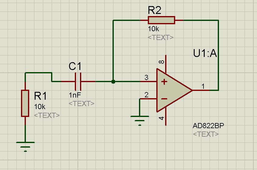
i can find the thevenin resistance in circuit such as Cap , Inductor and resistor network but in the op-amp circuit how can i find the thevenin resistance across of the cap pins in these circuit that i imagine to find the thevenin resistance (because i want to design a amplifier and want to find the response frequency with the Cap , cut frequency but now it is important to me to find the thevenin resistance in op-amp circuit)(ideal op-amp and unideal op-amp)

Thanks

Question number 1:
8442141200_1350674330.jpg

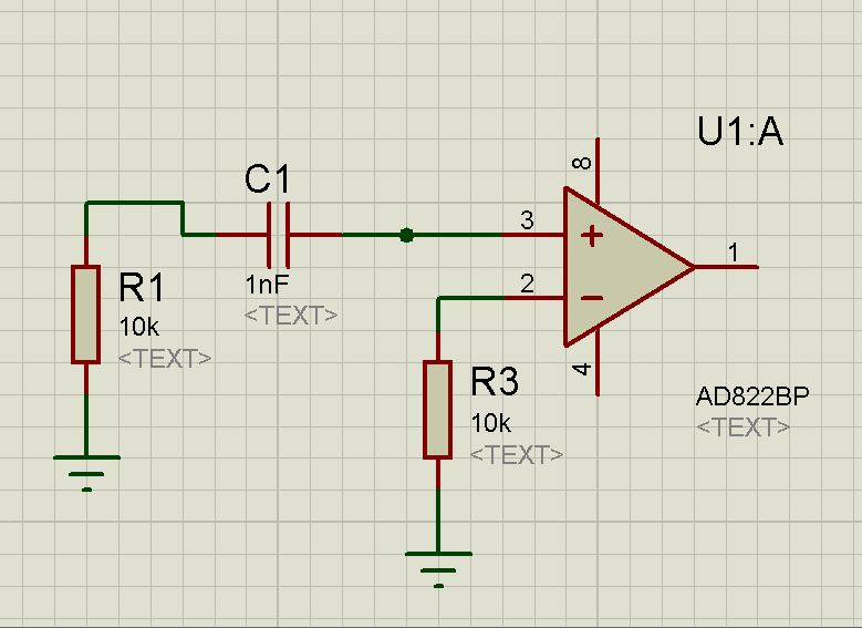
Question number 2:
1357748300_1350674331.jpg

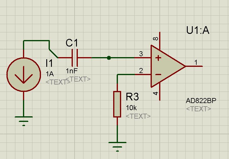
Question number 3:
4083344300_1350674332.jpg

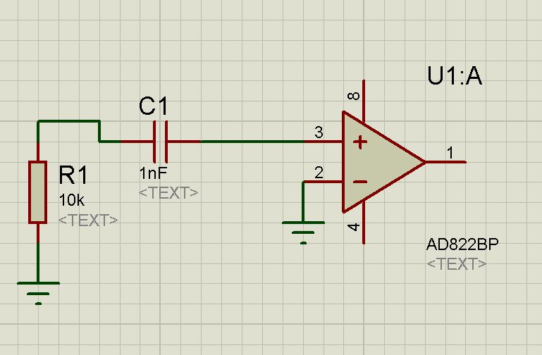
Question number 4:
9891500700_1350674333.jpg
 

The circuits without a current path for the OP input current can be sorted out from further analysis, I think. They don't represent working OP configurations.

Thevenins theorem applies to linear networks and has in so far limited significance for OP circuits. E.g. the floating OP input in three of the circuits will drive the OP into saturation and invalidate the analysis presumptions.

As long as the circuits provide a reasonable OP operation point, the circuit small signal behaviour can be analyzed by linear network methods.
 
  • Like
Reactions: LvW

    LvW

    Points: 2
    Helpful Answer Positive Rating
Hi baby_1

My recommendation to you:
Before starting to analyze some specific properties of opamp-based circuits you should try to become familiar with the basic principles of opamp operation (for example: proper biasing and negative feedback).
 
  • Like
Reactions: FvM

    FvM

    Points: 2
    Helpful Answer Positive Rating
Thanks dear friends
i know about the internal and external circuit of op-amps and analyze their circuit with node analyze.in above circuit that i imagine them i need only wants to calculate and find the thevenin resistance without feedback or without it(for example as a comparators).
 

Baby_1, are you aware that NONE of the circuits as presented in your first posting is able to operate as an amplifier?
 

hello dear LvW
i know that , none of them works as a amplifier , as i said before i image if we have one on the above circuit(also can't see none of them in environment) what resistance the cap see from its pins
 

You can either check the datasheet of the manufacturer for the opamp's input impedance or use the internal circuit (if one is given) combined with the parameters from the spice model (assuming it's open) to find a small signal equivalent of the differential input stage and calculate the resistance of that one. But frankly it doesn't matter much. Almost all opamps these days are based on FETs. As a professor once told me: "FETs don't do input resistance". 10 MOhm is low for a FET input stage. So unless you intend to hook up 100 MOhm resistors to your opamp you won't even need to take notice of it's input impedance in most cases. The better opamps their input resistance measures in the GOhm range. That's simply an open circuit. What you should really worry about is the drift and small current flow. It'll cause way more problems than not matching the impedances. Like in the first two circuits you need to put a resistor in the order of R2 between pin 2 and the ground to limit the current flow into the opamp. Another thing about the inverting amplifier setup is that the voltage at the input terminal is always equal to the voltage applied at the positive pin as long as the opamp doesn't saturate, minus the small voltage difference caused by the current flowing into the FET gates. So what you have is that one of your capacitor pins is attached to the ground. So you don't even need to consider the input resistance for calculating your high-pass filter here.

What you have at your input pin (the other capacitor pin) depends on where your source is attached. Thevenin doesn't work here without a source. Assuming you're talking about a voltage source you'll just have a high pass RC filter. If you're using a current source, convert it to a voltage source cause else you'll over complicate matters. In any case it'll just be the resistor you put there. In the case of the ideal current source you'll have an infinite resistance meaning your entire input is dictated by 1/(jwC).
 

Status
Not open for further replies.

Similar threads

Part and Inventory Search

Welcome to EDABoard.com

Sponsor

Back
Top