B
BlackMamba
Guest

Source: Termometr na wy
Project by szeryf.rm
Design background:
1.Device must be cheap. Device price exclude case and Power supply unit.
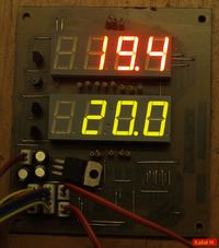
2.Temperature must be displayed on 7-segment LED displays. There should be two displays 4 digits each.
3.Two temperature sensor will be connected: one for external temperature, second one for internal.
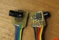
4.Temperature sensors should be digital. I have found TC77 sensors. They are very well documented and have interesting parameters: 13-bit result and 0.0625 resolution.
5.Accuracy should be better than +/- 0.5'C.
6.Measurement resolution should be 0.1’C
7.Measured temperature range should be from -30’C to +100’C.
8.Thermometer should be configured without using computer.
9.Temperature registration should be possible.
Scope of thermometer functions:
1.Calibration based on 28 measurement points for each sensor. Number of calibration points is user-dependent. These points are used for linear interpolation.
2.Calibration points may be entered manually or semiautomatically
3.Calibration points may be reviewed, added or deleted.
4.Defaults can be restored (without calibration and with cleared temperature registers).
5.Default EEPROM content can be restored (filling with 0xFF).
6.Additionally software has security function protecting EEPROM in the case when part of the data “volatilizes” in spite of setting BOD bits. Protection consists of two parts: checking correctness of data in EEPROM (parity bits for every byte and checksum) and correcting the data in EEPROM on the basis of copies of data.
7.Protection in the case of “volatilizing” RAM data. On the basis of checksum and parity bits circiuit checks the data error and reads data from EEPROM.
8.Possibility of previewing minimal and maximal temperatures for each sensor (temperature registers).
9.Possibility of clearing each of temperature registers.
10.Three temperature registers for each sensor. Each can be individually cleared.. Each register stores minimal and maximal temperature. First register holds daily temperatures. Second register holds week temperatures, third register holds month temperatures.
Smaller part of code was written in ASM, rest in C. Code written in C was optimized by creating additional optimizing functions.
Additional information:
temperature sensor works better with stable voltages, so two stabilizers were used to cut off sensor from the rest of circuitry.
Segments current varies from 7.5mA to 8.5mA depending on number of segments lit and ILED resistors (in my case they are 47kohm resistors)
Green segments lit a bit smaller because identical ILED resistors were used for both displays.
Heat is emitted only by stabilizer.
Summary:
Thermometer is based on two sensors and two LED displays.
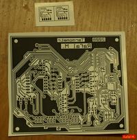
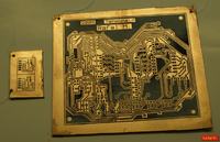
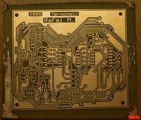
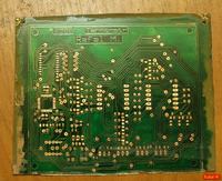
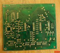
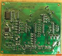
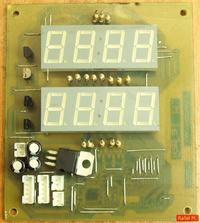
pcb diameters: 84x97 mm
possibility of calibration and good accuracy in full range of temperature measured.
Three minimum and maximum temperature registers for each sensor
Two-button control
Stabilized power supply 8V 1A minimum
Temperature range from -30 to +100 with possibility of change.
