Continue to Site

Welcome to EDAboard.com

Welcome to our site! EDAboard.com is an international Electronics Discussion Forum focused on EDA software, circuits, schematics, books, theory, papers, asic, pld, 8051, DSP, Network, RF, Analog Design, PCB, Service Manuals... and a whole lot more! To participate you need to register. Registration is free. Click here to register now.

thermocouple to 741 opamp

Status
Not open for further replies.

smitgovani

Member level 2
Member level 2
Joined
Dec 25, 2011
Messages
50
Helped
3
Reputation
6
Reaction score
3
Trophy points
1,288
Activity points
1,641
i have connected j thermocouple to 741 op amp in proteus...but physically i am not able to connect ..!!
where 2 pins of thermocouple connected etc..i m new so plz help me
 

I can't help you with Proteus but normally you would connect it between one of the 741 inputs and ground.

I doubt it would work in real hardware, the output from a thermocouple is very tiny and would probably get lost in the noise generated by a real 741 op-amp. You would also have a problem with making connections without introducing further temperature related errors and you should ideally have some sort of ice-point compensation.

Brian.
 
  • Like
Reactions: wendmu

    wendmu

    Points: 2
    Helpful Answer Positive Rating
The basic TC sensor amplifier is an OP in non-inverting amplifier configuration. A cold junction compensation should be added, as betwixt mentioned. The most simple variant uses a silicon diode as temperatur sensor for the compensation, also copper RTD has been often used in classical industrial temperature controllers with TC input.

Noise of 741 isn't necessarily a problem with respective low amplifier bandwidth, but offset voltage and offset voltage drift surely are. OP07 would be a good low offset standard for a TC amplifier.
 
cant get u clearly.......can u illaborate by any ckt??
 

Google "thermocouple amplifier" for examples. I have used the AD595 very successfully in the past.

FVM - sorry for my bad wording, what I meant by 'noise' was a total effect of all bad properties of a 741 rather than in the random electrical sense.

Brian.
 

can u send me any circuit so that i can understand ..i think i also have 2 use ad594
 

look if i m using ad594 amplifier ic what i m getting??
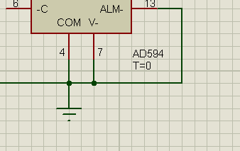
o/p should be 8181mV ad594.jpg
 

Please explain why you think it should be 8.181V, if built correctly it should be 10mV/C.

If you are measuring from a real device, you must follow the guidelines in the data sheet. The thermocouple connections and the IC itself should be at the same temperature and the wires must be connected using the same method. Remember that a thermocouple generates voltage at the point where the two dissimilar metals meet. The same applies at all the other junctions between the thermocouple and the IC, this includes solder joints at the thermocouple wires, the PCB and the IC pins themselves.

Brian
 

i have applied 750 degree C....so that o/p of ad594 should be 8181mV according 2 datasheet...
but coming -192.9mV...something wrong.....
is my ckt is wright??
 

8.18 is the nominal output voltage with 750 °C TC temperature according to AD594 datasheet.

You'll most likely guess, that it's not achieved with 5V supply voltage. :lol:

In addition, to get reasonable absolute voltage numbers, you should have a ground label connected.
 
opamp.jpg

noe i have attached 12V still displaying answer in minus....
and if i connect ground but how i connect it practically???
how to connect with ground (0V)???
 

ad594.jpg

sorry it was wrong image..
this 1 is right
 

i m taklking about practically connection ....practically how i connect to 0V?
 

I'm talking about practical connection, too. But I'm not sure, if I understand the question.

85_1334436191.gif
 

ok u have connected pin 4,7,13 to ground but i m making hardware of this
then where i connect those pins???
if u r saying to negative supply..then o/p voltage coming not 8181mV
 

I was talking about simulation so far. You have been asking, why you see wrong results, and I answered this question. It's primarly a simulation problem. For requirements of the real device, refer to the datasheet, as betwixt suggested.
 

I used to make and sell a simple temperature gauge that used a K-type thermocouple and a LED bar-graph readout.

Here is the very simple circuit which used a CA3140 op-amp;

https://i44.tinypic.com/2eq6yqa.jpg

The range of temperature was, iirc, 450C with one LED lit to 700C with all seven LEDS lit. I only used seven of the available ten LED outputs of the LM3914.
 
  • Like
Reactions: wendmu

    wendmu

    Points: 2
    Helpful Answer Positive Rating
All grounds are -Vcc; the circuit operated from a single 9v battery with the - terminal grounded.
 

Status
Not open for further replies.

Similar threads

Part and Inventory Search

Welcome to EDABoard.com

Sponsor

Back
Top