Vermes
Advanced Member level 4

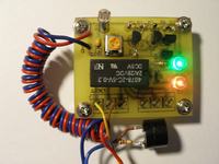
The system consists of a voltage divider on photoresistor and potentiometer, Schmitt flip-flop and signal inverter on transistors BC547 and emitter duplicate also on BC547.
List of components:
- R1 – photoresistor
- R2 – 10k
- R3, R4 – 200ohm
- R5 – 9,1k
- R6 – 100k
- R7 – 510ohm
- R8, R9 – 10k
- PR1 – 10k
- Q1, Q2, Q3, Q4 – BC547
- D1 – 1N4148
- D2, D3 – LED 5mm
- C1 – 100nF
- REL1 – 4078-2C-5V-0.2
- ARK1, ARK2 – 3 x 5mm
- supply voltage: 5V – 12V
- power: 0,31W – 0,90W @ 12V
- 0,06W – 0,15W @ 5V
- dimensions: 47mm x 41mm x 15mm
https://obrazki.elektroda.pl/3456071000_1312739576_thumb.jpg][/url]
Pictures for making the PCB:
[img]https://obrazki.elektroda.pl/9022943200_1312739576.png
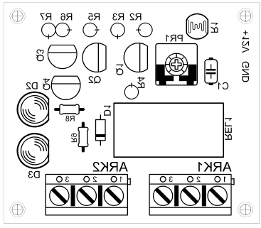
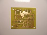
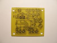
Photos of the PCB and assembled system:
[url=https://obrazki.elektroda.pl/8402097900_1312739572.jpg]
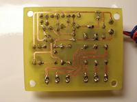
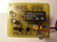
Video with operation of the system:
Link to original thread – Włącznik zmierzchowy z histerezą
Last edited: