palmeiras
Full Member level 6

- Joined
- Feb 22, 2010
- Messages
- 375
- Helped
- 61
- Reputation
- 122
- Reaction score
- 50
- Trophy points
- 1,308
- Location
- South America
- Activity points
- 4,199
Hi everybody
I have designed one traditional BGR as shown in figure 1.
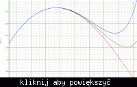
And I didn’t achieve the corrected and expected curvature of the output voltage, when I used vertical parasitic PNP2 (emitter area =2x2). The output generated by this reference is shown in figure 3. As one can see, at high temperatures, the output voltage increases a lot. There is no value for the aspect ratio of the resistors that overcames this effect.
However, when I used PNP10 (emitter area = 10x10), the output voltage, generated by this SAME reference, is corrected. It is shown in figure 2. It doesn’t increases at high temperature.
Why??? Why isn’t it possible to achieve the corrected curvature with PNP2?
The values of BETA for both devices (PNP2, PNP10) are similar:
BETA_PNP2 @27=2,614
BETA_PNP10 @27=2,633
BETA_PNP2 @120=4,072
BETA_PNP10@120=3,869
Obs: I used an ideal op-amp (described in verilog-ams) in this design.
Thanks!


