Continue to Site

Welcome to EDAboard.com

Welcome to our site! EDAboard.com is an international Electronics Discussion Forum focused on EDA software, circuits, schematics, books, theory, papers, asic, pld, 8051, DSP, Network, RF, Analog Design, PCB, Service Manuals... and a whole lot more! To participate you need to register. Registration is free. Click here to register now.

testing PNP saturation threw pulse "delay" shape

yefj

Advanced Member level 4
Joined
Sep 12, 2019
Messages
1,404
Helped
1
Reputation
2
Reaction score
5
Trophy points
38
Activity points
8,544
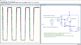
Hello,I have attached two LTSPICE files.There are two kinds of plots,saturated and non saturated shown below.
I dont understand where is the significant delay in the signal in the saturated state.
How can i see that there is stretch in the non saturated PNP?
Saturated PNP
1724488738398.png

1724488760248.png


NON Saturated
1724488722357.png
 

Attachments

  • ltspice.zip
    1.6 KB · Views: 17
Get your logic diagram to conform. Positive high.

Balance your bias and don't saturate the base.
Then prevent Vcb > Veb with a clamp diode.

1724506735698-png.193305
 

Attachments

  • 1724506735698.png
    1724506735698.png
    148.3 KB · Views: 70
  • BJT-saturation.ts.zip
    912 bytes · Views: 18
Models lie. Have seen many which have real delays in us
range with model TR set to ns values. Do you see any
mfr recovery time spec to validate model behavior? Or
have you ever gone and set up the bench test jigs to
do it for real, as I think was suggested?
 

LaTeX Commands Quick-Menu:

Part and Inventory Search

Welcome to EDABoard.com

Sponsor

Back
Top