rajeshree
Junior Member level 2

Hello every one,
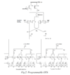
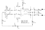
I have attached design of programmable OTA. but i dont know how to measure parameters like gain, phase, CMRR, PSRR, slew rate etc. To measure all this parameters i have used one test bench which is also attached here.
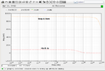
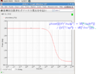
But problem is that i have measured gain in db, which is negative and phase is also negative.
In test bench there are 3 output terminals two of them are outp and outn but third one is cmref. where can i connect in my design? and what are the suitable values for all R and C in test bench. is it correct test bench?
How can i get positive phase and gain(dB)? i have attached these graphs also.
please give me suggesion
Thanks in advance


