Vilius_Zalenas
Newbie level 4

Hi,
I am an analog/power electronics beginner. I have a task to generate nearly 200V AC voltage already having a 18.4V DC rail, but I faced massive distortion and transformer ringing problem...
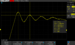
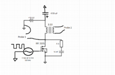
In the beginning, I decided to go with a 1:10 pulse transformer and extremely simple switching circuit. I am using a pulse transformer (MPN: 750032050) and N mosfet (IRF 3205). I hooked everything up on my breadboard, and turned on an oscilloscope to see what is happening. So the first picture is what I saw immediately (picture 1): both windings have extremely weird higher order harmonics coupled into the 110 kHz square signal, also there was huge voltage spike every period. After some more research, I decided to put a snubber circuit for the mosfet and I decided to disassemble my breadboard and solder everything down to an example board (to ensure perfect contacts and minimize all parasitic parameters). I provide the formulas ( which I used to determine the RC snubber parameters) in the picture. So the second time (after soldering and adding a snubber branch) I saw this (picture 3): the voltage spike is still present and the signal is nothing similar to a square form (as it should be).
Some more additional info:
1. I checked my wiring many times (it is right)
2. I am driving the mosfet from PIC32 (I am using a high current PWM pin, which is set to 110 kHz and supplying 12-13 mA of current)
3. My 18.4V rail is capable of supplying up to 1A of current. I measured the transformer current (in the operating state), it was around 370 mA, so I dont think I have a supply rail problem (the mosfet gets only warm, but not hot...)
4. The datasheet of the transformer says its operating frequency is 100 - 400 kHz, so I picked 110 kHz PWM in order to keep the frequency as low as possible to minimize the turn on and turn off mosfet delay effects to the signal.
I am not sure if I am putting enough current into my mosfet gate, I was thinking to buy a mosfet driver, but then again, 110 kHz is not an extreme frequency... (maybe you can recommend me a good driver for the given parameters). Besides the mosfet gate current, I dont have any other ideas on how to make it work properly. So I am kindly asking for any advices on how to setup that magic pulse transformer circuit (to get something similar to square signals). I thank you in advance
Vilius


