Continue to Site

Welcome to EDAboard.com

Welcome to our site! EDAboard.com is an international Electronics Discussion Forum focused on EDA software, circuits, schematics, books, theory, papers, asic, pld, 8051, DSP, Network, RF, Analog Design, PCB, Service Manuals... and a whole lot more! To participate you need to register. Registration is free. Click here to register now.

Switching power supply input/output current relation & transformer rating

Status
Not open for further replies.

alexan_e

Administrator
Advanced Member level 7
Joined
Mar 16, 2008
Messages
11,888
Helped
2,021
Reputation
4,158
Reaction score
2,031
Trophy points
1,393
Location
Greece
Activity points
64,371
Hi

I have a doubt about the operation of a switching power supply and I would appreciate your feedback.

Suppose that we have a transformer rated at 1A , we are using a full wave bridge and a capacitor and suppose that the rectified output is 12v DC.

If I use a switching regulator (like LM2576 or LM2676 etc) but with an efficiency of 100% (imaginary for this example) and set the output to 6v with a 3 ohm resistor connected to the output as load (for 2A load current) then will this operate?

I would expect the regulator to work with a 50% duty to provide 6v output but this 50% would require 12v/2A pulses and the transformer can only give 1Amp so what will happen?
Is the transformer able to give pulses of higher current that the rated one as long as the average current is 1A (like 50% 2A or 25% 4A) or will all this current be provided from the bridge capacitor and the transformer will never give more than 1A?
Should the bridge capacitor be calculated for 2A instead of 1A in this case?

Thank you
Alex
 

I can give you a practical experience. You know I have used a 0.2 V battery (worn out battery) to glow an LED. That indicated that the current have been increased. You can google it. The circuit is called as Joule thief. I have got this circuit from internet. Hope this helps you...
 

I thing your example does the opposite, it increases the voltage to glow the led since a led would need more than 1.5v to glow.

In any case a battery is very different because it can provide the higher current to the switching regulator but my question is specific to the behavior of the transformer.

Alex
 

I have no idea If I didn't explain properly my question or if it is a stupid question.

Maybe a schematic would help you understand what I mean
LM2576.GIF

Can the 12v/1Amp transformer be used with a circuit like this to give 6v/2A (with the assumption of 100% efficiency)?

Alex
 

I am just keeping my views below:

1) I think if the energy source (transformer in this case) itself cannot source 2A of current then how come we can get more than that at the output.

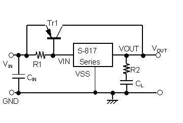
2) Normally in case of normal voltage regulator the excess current needed is acquired from the input itself (as shown in the attached ckt diagram).

Ignore if you feel its a stupid answer.

81_1321970964.jpg
 

I appreciate your answer very much.

In order to output 6v output from 12v input the regulator (ideal model) will work with 50% duty ratio , that means that it needs 12v/2A 50% duty pulses to provide a constant 6v/2A in the output.

The 12v/2A 50% gives an average current of 1A which is within the transformer rating so I think that either the transformer is able to give more current that the specs as long as the average is 1A or the transformer charges the bridge capacitor with rate of 1A and the capacitor discharges with a rate of 2A with a 50% duty , in this case that seems more logical the capacitor should be able to do that.

Alex
 

the transformer charges the bridge capacitor with rate of 1A and the capacitor discharges with a rate of 2A with a 50% duty

This seems to make sense for constant load I guess... What If the load is a varying load???

If load varies there is a possibility of mismatch in the RC constant.
 

In the schematic above I have uses a switching regulator that changes the duty ration in order to keep the voltage constant in the output , as long as the load draws <=2A the capacitor charge will be able to cover it (ideal conditions 100% efficiency which is only theoretical of course, the real is about 70-75% for the specific ic).

If my assumption is correct then gues you can use a 30v 1A and get in the output 5v/3A without a problem in a real circuit but the question is what size of capacitor to use in the bridge.
Using the 1000uF/A rule I assume that we calculate it based on the output current so about 3000uF should do.

I would still like someone to verify is this assumptions are correct.

Alex
 

This shouldn't be a problem for the transformer. Its leakage inductance will likely act to block the high frequency switching currents from flowing in the windings. The vast majority of the input ripple current should flow through the input capacitor, so long as it is a nice low impedance. In fact you should be more concerned about the high peak currents due to the bridge rectifier+large capacitor, not the buck converter.

3000uF sounds about right. If your regulator gives 6V and 2A out at ~%80 efficiency, then you'll be drawing 15W from your capacitor bank, or 0.125J per every rectification cycle (assuming 60Hz line frequency). So your capacitor has to be able to deliver 0.125J and still be above 6V. 3000uF should do the job.
 
I have a 50Hz mains.
Since I use a full wave bridge I should use 100Hz to calculate the energy for every rectification cycle,
so it should be 15w * 1/100 = 0.15J

The formula for the energy stored in a capacitor is E = 1/2 * U^2 * C

Where
E = Energy in capacitor in joules
U = Voltage in capacitor in volts
C = Capacitor capacitance in farads

How did you calculate the last part with the remaining voltage level on the capacitor?
Will the 6v remaining capacitor voltage be enough to give the output of 6v or I must calculate for a higher remaining voltage?

Thank you
Alex
 

I have a 50Hz mains.
Since I use a full wave bridge I should use 100Hz to calculate the energy for every rectification cycle,
so it should be 15w * 1/100 = 0.15J

The formula for the energy stored in a capacitor is E = 1/2 * U^2 * C

Where
E = Energy in capacitor in joules
U = Voltage in capacitor in volts
C = Capacitor capacitance in farads
Right, that's how I did it.
How did you calculate the last part with the remaining voltage level on the capacitor?
If you have a 3000uF capacitor at 12V and take away 0.125J, then the capacitor will have 7.8V left on it, as per the formula you posted.
Will the 6v remaining capacitor voltage be enough to give the output of 6v or I must calculate for a higher remaining voltage?
Looking at the datahseet I see that those regulators use a darlington as the power switch, which basically subtracts 1.4V from your input voltage. I would try to keep the input voltage from sagging below 8V. Also that darlington will kill your efficiency a bit (maybe down to 70-75%. I don't even know why people still use the things)). And your 50Hz line frequency means the caps should be a bit bigger.

Taking that all into account, you'll need to deliver 0.171J per 100Hz cycle. To keep it from drooping below 8V, you'll need at least 4300uF.
 
I don't even know why people still use the things
I bought 10 of these regulators (ADJ) in an auction in ebay for $2.25 including shipping so it was a good deal :-D
Actually a have always used 7805 or LM317 and these switching regulators are much more efficient although you are correct that in the switching regulator category there are many far better choices using mosfets.

Anyway since I haven't worked with these regulators before I was trying to understand if I could use some of the transformers I have (pulled from broken devices) that I couldn't use with my linear regulators, transformers like 35v/1A or 28v/0.5A.
The example of the transformer was just a rating to help with the calculations of my example.

If I ware to buy a transformer from a project then I would definitely use a transformer voltage close to the needed output but this was more about the possibility of using a high voltage low current transformer to get a low voltage high current output (with 5v or 3v3 output).

From what I understand so far it seems possible but there are some calculations requires and of course a good quality capacitor for the bridge.

Alex
 

Status
Not open for further replies.

Similar threads

Part and Inventory Search

Welcome to EDABoard.com

Sponsor

Back
Top