Continue to Site

Welcome to EDAboard.com

Welcome to our site! EDAboard.com is an international Electronics Discussion Forum focused on EDA software, circuits, schematics, books, theory, papers, asic, pld, 8051, DSP, Network, RF, Analog Design, PCB, Service Manuals... and a whole lot more! To participate you need to register. Registration is free. Click here to register now.

Supplementary insulation / protection

bodewonkinobe

Newbie level 6
Newbie level 6
Joined
Jul 26, 2018
Messages
13
Helped
0
Reputation
0
Reaction score
0
Trophy points
1
Activity points
167
Hi all

I am designing an isolated voltage channel within a portable product (a high end portable DMM) which I require 1000V CATII and 600V CATIII rating on the measurement inputs

I am designing to IEC61010.

The product is powered/charged by a DC wall adapter or can be run on its internal batteries.

I am using isolators from analog devices which provide 600V reinforced CATII, but not CATIII

the product has a plastic injection moulded case and some metal BNC/USB ports

In the past I have designed products with metal cases and achieve secondary insulation / protection to bring CATII up to CATIII by using the earth bonding protection as the secondary level of protection.

Now, I need to bring the CATII up to CATII, I cannot rely on the plastic enclosure to add that secondary level of protection, as there are exposed metal parts ….

So, bearing in mind that this is a portable device would it be a good approach to achieve a secondary level of protection by including a protective earth terminal on the metal parts, and internally bond any exposed metal parts together and put a clear warning notice on the product that the product must be safety earthed using the terminal (maybe only if the measured voltages exceed the reinforced levels of insulation achieved by the isolators alone?)

Normally the protecting earth is achieved via the wall power adapter, but in this case there isn’t one - is there anything I’m missing here? Or can I just simply add a protective earth terminal and make it clear to the user it must be connected to protective earth in the installation they are measuring if they exceed X voltage ?

Thanks !
--- Updated ---

I could rephrase the question or summarise it as….

Can I have an earth protection terminal on a handheld product? In order to provide supplementary insulation/protection ?

does it violate any rule I haven’t perhaps caught in my review of iec61010 that says a portable instrument cannot have a protective earth terminal that must be used for X Y and Z situations ?
 
Last edited:
Protective bonding doesn't sound like a practicable solution here.
SELV circuit part includes external USB and BNC connection, you need to guarantee that none of the external connected signals can carry dangerous voltage. It's not sufficient to have a low impedance connection of ground net.
 
Electrical products of protection class II have a reinforced or double housing insulation. The housing does have electrically conductive components – but these cannot be live due to the design. Such products are therefore electrically safe to touch by virtue of their construction. They therefore do not require a protective conductor. Thus, no protective earth resistance test is possible or necessary.
REF: https://www.schleich.com/en/the-protective-earth-test/

PPG (below looks like overkill) but if using a meter on a CAT III environment (high power) Arc Flash Protective Gear is necessary, just in case meter exceeds contamination level and arcs. Although TV repair guys used to routinely test 25kV safely with 100:1 to 500:1 probes, it was relatively low power, and would not cause spontaneous human combustion (SHC) as might a CAT III arc flash. Ref https://enesproppe.com/
1701050846234.png

PPE & PPG
REF https://www.ecmweb.com/maintenance-...6/the-basics-of-personal-protective-grounding

Reference Specs https://www.fluke-direct.com/files/fluke-multimeters-detecting-intermittents-u.pdf
Fluke 190 III ratings

Altitude Operating up to 2000 m (6 600 ft)
All terminals to earth: CAT IV 600 V, CAT III 1000 V
BNC input shield to center pin CAT IV 300 V

Operating above 2000 m and up to 4000 m (13 000 ft)
All terminals to earth.: CAT IV 300 V, CAT III 600 V, CAT II 1000 V
BNC input shield to center pin CAT IV 150 V, CAT III 300 V

1701051374139.png


My comment: The 2 ohm source is the source R on the impulse on CAT III HV test raises the Q if tested on a long cable say 0.5uH/m with meter input capacitance can cause high Q ringing, so keep input capacitance as low as possible. I would design it for 8kV BIL. (basic impulse level)
1701051826977.png


Safety info
 
Last edited:
Protective bonding doesn't sound like a practicable solution here.
SELV circuit part includes external USB and BNC connection, you need to guarantee that none of the external connected signals can carry dangerous voltage. It's not sufficient to have a low impedance connection of ground net.

Bear in mind while this can be moved around and battery powered, it’s still intended to be used on a Laboratory bench….

So I was hoping to use the same approach as some voltage probes use which stipulate that the protective earth needs to be connected to use in a CATII environment

95% of use will be in a CATII situation after the socket and fuse protected

An example of the isolator used is the ADN4624

This provides reinforced insulation of 600Vrms per IEC60747-1.

It also has VDE 0844 classification to 600Vrms CAT I to IV
--- Updated ---

Electrical products of protection class II have a reinforced or double housing insulation. The housing does have electrically conductive components – but these cannot be live due to the design. Such products are therefore electrically safe to touch by virtue of their construction. They therefore do not require a protective conductor. Thus, no protective earth resistance test is possible or necessary.
REF: https://www.schleich.com/en/the-protective-earth-test/

PPG (below looks like overkill) but if using a meter on a CAT III environment (high power) Arc Flash Protective Gear is necessary, just in case meter exceeds contamination level and arcs. Although TV repair guys used to routinely test 25kV safely with 100:1 to 500:1 probes, it was relatively low power, and would not cause spontaneous human combustion (SHC) as might a CAT III arc flash. Ref https://enesproppe.com/
View attachment 186487
PPE & PPG
REF https://www.ecmweb.com/maintenance-...6/the-basics-of-personal-protective-grounding

Reference Specs https://www.fluke-direct.com/files/fluke-multimeters-detecting-intermittents-u.pdf
Fluke 190 III ratings

Altitude Operating up to 2000 m (6 600 ft)
All terminals to earth: CAT IV 600 V, CAT III 1000 V
BNC input shield to center pin CAT IV 300 V

Operating above 2000 m and up to 4000 m (13 000 ft)
All terminals to earth.: CAT IV 300 V, CAT III 600 V, CAT II 1000 V
BNC input shield to center pin CAT IV 150 V, CAT III 300 V

View attachment 186488

My comment: The 2 ohm source is the source R on the impulse on CAT III HV test raises the Q if tested on a long cable say 0.5uH/m with meter input capacitance can cause high Q ringing, so keep input capacitance as low as possible. I would design it for 8kV BIL. (basic impulse level)
View attachment 186489

Safety info

Thanks for the reply

But this doesn’t give any clarification of whether or not providing an earthing terminal in order to provide supplementary protection in circumstances where it is required on a handheld product is “ok” or not ….

Looking at the specs of the isolators, they actually offer reinforced isolation to 600Vrms CAT IV. But I need to read the datasheet another 20 times to be sure!

I can accept 600V rating, it would just be nice to achieve 1000V
 
You find similar isolation and ground concepts e.g. with differential osciloscope probes like SI9001.

1701074890888.png


The operation instructions specify:
Must be Grounded
This probe is grounded with the shell of BNC connector and an auxiliary grounding terminal, through the grounding conductor of the power cord of the measurement instrument. Before making connections to the input leads of this probe, ensure that the output BNC connector is attached to the BNC connector of the measurement instrument and the auxiliary grounding terminal is connected to a proper ground, while the measurement instrument is properly grounded.

Use Fused Test Prods if Necessary
If this probe is intended to use for measurements in circuits of INSTALLATION CATEGORY III, it should incorporate with fused test prods.
--- Updated ---

I believe, that the grounding requirement has been primarly specified due to significant DC common mode current of several 100 uA caused by the resistive input divider. Although the input current is considerably below safety limits, it could charge a non-grounded instrument to possibly damaging common mode voltage.

Insufficient voltage strength for double insulation may be also an issue.

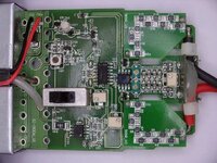
10270002b.jpg
 
Last edited:
Ground leakage currents may be connected via dust and humid air.

A "Ground" definition is simply any node you define as 0V but a safety ground might not be 0V but is low enough impedance to divert unwanted currents to be safe.

It may be necessary to have 1Meg ground matts to reduce the risk of ESD voltages from triboelectric (motion-charge) activities or have protect gear for the user (rubber gloves) and PPG so that insulated probes can be attached.

But if the creepage resistance of dust and humidity can induce harmful voltage to electronics, then active or passive guarding techniques are often used to attenuate ingress leakage. Also TVS or similar clamp components after current limiting attenuation are used for EEG amplifiers as long as the resistor voltage rating is high enough for the category type impulse test. It is useful to know sometimes that DC breakdown voltage can be only 10% of the 1us risetime impulse test BIL rating. e.g. a BIL 200kV ceramic insulator can start discharging at 50kVAC or DC in relatively clean circumstances This is due to the delay of ionization in air due to the risetime of equivalent RLC circuit of a potential arc gap to reach to detonation voltage breakdown threshold of air. After the arc the incremental resistance is negative and inverse to the capacitance and Q and thus arc current waveform. For fingers the current risetime can be in picoseconds but for lightning it tends to be in the 1 us range which is easily detected on any AM radio.

useless additional info

Finger ESD or UHV partial discharge (PD) can be detected using any E-field meter or radio from acoustic, ultrasound, VHF, UHF, IR, Visible, UV and possibly Gamma waves (although the latter is typically used for detecting sunspot or galactic discharges beyond the scope of this question, but I thought to mention it even if occured 20 million light years ago.) But to tie back to my original point our Ozone layer and magnetosphere provides passive guarding to such high energy events. Where else can we get a supplementary protective ground (SPG)? A mineshaft? Cu/Pb Faraday Cage (satire warning ;)
 
Why would you have a ground socket to a plastic case in a double insulated instrument?
The ground terminal will be on the exposed metal parts not the plastic case. As I mentioned, the main case is plastic… but there are also exposed metal parts which I will mount onto a metal plate so that it can all be bonded together.

This isn’t a truly double insulated product … even those the majority of the case is indeed plastic… This is because there are communication ports which the user needs to access which are metal (on the non isolated side of the product, the USB, RS232 and LAN port PCB…)

I have now determined that the isolators used will only provide reinforced isolation up to 300V and basic insulation up to 600V.

So I will have to either bond the exposed metal parts to achieve supplementary insulation/protection or use some other method…
--- Updated ---

You find similar isolation and ground concepts e.g. with differential osciloscope probes like SI9001.

View attachment 186490

The operation instructions specify:

--- Updated ---

I believe, that the grounding requirement has been primarly specified due to significant DC common mode current of several 100 uA caused by the resistive input divider. Although the input current is considerably below safety limits, it could charge a non-grounded instrument to possibly damaging common mode voltage.

Insufficient voltage strength for double insulation may be also an issue.

View attachment 186491
Yes this is exactly what I am thinking of doing in order to meet the requirements of CAT III for my design

I smiled when seeing your picture , because even though I have never seen that probe PCB to copy it … my attenuator looks very similar!

the equipment will be used in the laboratory, by competent design engineers… I feel it’s reasonable to state that a safety ground should be used if it os being used in a CAT III environment or above 300Vrms
 
Last edited:
Why would you have a ground socket to a plastic case in a double insulated instrument?
The exposed metal on the instrument deserves to have a supplementary ground rated for 20A, the usual test.
 
The exposed metal on the instrument deserves to have a supplementary ground rated for 20A, the usual test.
Yes this is my thought too

The isolators provide reinforced isolation to 300Vrms

Would it be feasible to state something like;

“Up to max 300Vrms CAT III, or max 600V CAT III providing instrument is safety earthed via supplied earth connection to terminal X”.

This would be on the display panel and next to all inputs.

the product is aimed at design engineers.
--- Updated ---

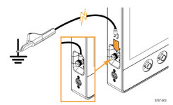
I found this in the tektronix portable oscilloscope manual


Warning: To avoid electric shock, connect the side ground lug external chassis ground point to earth ground when operating the instrument from battery power.
Without a connection between the chassis and earth ground, you can receive a shock from exposed metal on the chassis if you connect an input to a hazardous voltage (>30 VRMS, >42 Vpk). To protect yourself against possible shock, you can attach the Tektronix-supplied grounding cable from the ground lug terminal on the side panel to earth ground. If you use a different grounding wire, it must be at least 12 gauge.”

I would say my solution is far safer as my input channels are fully isolated, I am only needing the bonding for supplementary isolation whereas they actually need it to keep the unit chassis at ground
 

Attachments

  • 918D9018-411F-4BFD-B465-1B0EB566C78B.jpeg
    918D9018-411F-4BFD-B465-1B0EB566C78B.jpeg
    162.6 KB · Views: 92
Last edited:

LaTeX Commands Quick-Menu:

Part and Inventory Search

Welcome to EDABoard.com

Sponsor

Back
Top