Continue to Site

Welcome to EDAboard.com

Welcome to our site! EDAboard.com is an international Electronics Discussion Forum focused on EDA software, circuits, schematics, books, theory, papers, asic, pld, 8051, DSP, Network, RF, Analog Design, PCB, Service Manuals... and a whole lot more! To participate you need to register. Registration is free. Click here to register now.

Super 'All Purpose' SMPS Suggestions (12-415V input)

Status
Not open for further replies.

BoBtHePlUmBeR

Junior Member level 2
Joined
Oct 23, 2007
Messages
23
Helped
8
Reputation
16
Reaction score
0
Trophy points
1,281
Activity points
1,465
Hi Guys,

I am currently deciding whether or not it is possible to design an all-encompassing supply for a new project I'm working on and would like some feedback (no pun intended) if anyone has any thoughts / suggested reading material they can help me with.

ps - I am more into the micro/software side of things, so please go easy on me!

I'm looking to design a supply with the following specs:
input voltage range : 20 - 415V (or 12-415 preferably)
input frequency : 50-60Hz
input voltage type : AC (although DC would also be handy)
input isolation : preferable

efficiency : doesn't matter - can draw plenty of power, as long as it doesn't get too hot.
size constraints : must be fairly small (footprint/height of approx 1inch cube)

output voltage : regulated 5V DC
output current : up to 1A

Cheers,
BoB
 

Everything over here is possible but the input voltage looks rather scary. 20 to 415v? Are you serious? You could have two parts of the PS. One where input is 80-415v, another where it's 12-80v. That would make much more sense. If you use SMPS, input can be either DC or AC as the input stage will have a bridge rectifier. 5v 1A at a small footprint possible.

Since you bring up micro, are you using microcontroller for this? I hope not, 'coz 1A 5v is simple enough with discrete small footprint chips, such as TOP, TNY, LNK, DPA, VIPER, etc.
For TOPswitch, TNYswitch, LNKswitch (also called LiNear Killer), DPAswitch go to Welcome To Power Integrations | Power Integrations
For VIPER, goto www.st.com

Fairchild, ON and other companies also offer their controllers, but I don't know much about them.

Hope this helps.
Tahmid.
 
Hi Tahmid,

Thanks for the reply!

input voltage looks rather scary. 20 to 415v? Are you serious?

Indeed I am serious. There is not really enough room to put in two seperate supplies, and it is quite possible that the device could be powered from 12-48V or directly from 415V.

Since you bring up micro, are you using microcontroller for this?

Don't worry - I was looking at using some kind of discrete. The guts of the device will have a micro, but I am definately hopeing to seperate the supply right out. This will enable me to re-use the supply design for other similar projects which would dramatically reduce development time!

For TOPswitch, TNYswitch, LNKswitch (also called LiNear Killer), DPAswitch go to Welcome To Power Integrations | Power Integrations
For VIPER, goto www.st.com

Fairchild, ON and other companies also offer their controllers, but I don't know much about them.

Thanks for the info - I'll be looking this up in more detail and let you know how I go.

Cheers,
Aaron
 

Hi,
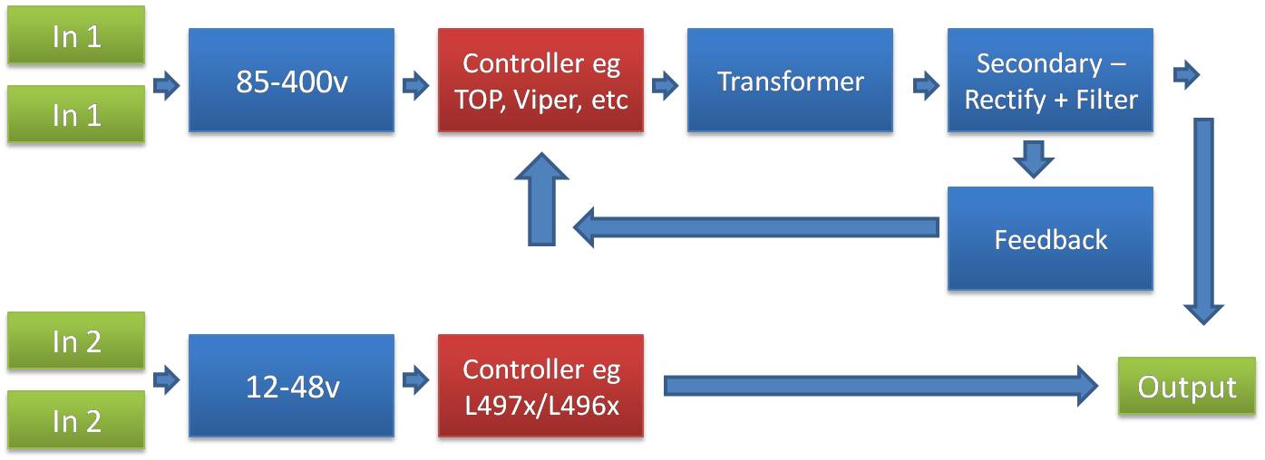
For practical safety purposes, you SHOULD put in two supplies, let me simplify it like this:
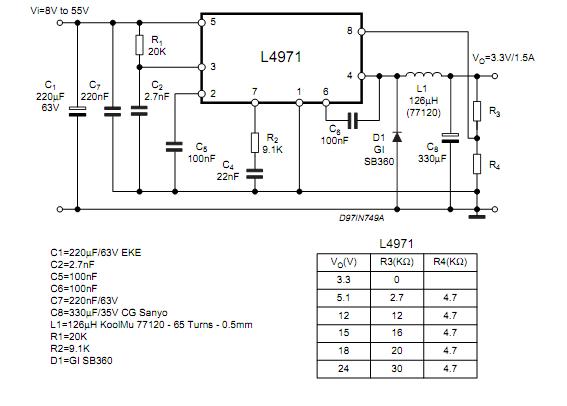
46_1289889300.jpg


72_1289889394.jpg


If you use one supply, you'd be pushing the switch beyond practical limits. If you have a buck, 12v means (1200/415) = 2.9% duty cycle, where you'll have peak currents of 15x - 30x operating current.

Hope this helps.
Tahmid.

---------- Post added at 07:42 ---------- Previous post was at 07:36 ----------

As you see, the L4971 can be fitted in a very small area as well as the other part.
 
  • Like
Reactions: klauss

    klauss

    Points: 2
    Helpful Answer Positive Rating
hi aron,

i too agree with tahmid.. this i/p voltage range s indeed frightening..and i'd say your size concern is also doubtful. with converter inductor, obvious transformer switches and their heat sinks..if you 're using micro that can also be a concern. then i suggest to do the pcb design from outside since you were more towards low power electronics. pcb design at high power levels is of some concern.

then, i suggest you for controllers Analog, Embedded Processing, Semiconductor Company, Texas Instruments where you can order samples of these control ics.you 'l get ordered ics within 1week.

regards :)
 

Hi,
You should carefully study the circuits using TOP, VIper or any on of these controllers, as these contain the control section and the power section of your circuit and also available in 8-pin PDIP. An EE15 or similar would do the job nicely. The L4971 is 8-pin PDIP as well. Should easily be fitted in a small enclosure.

Hope this helps.
Tahmid.
 

Hi Tahmid & abhijithvp,

Thanks for the diagram Tahmid, it is very clear what you are suggesting here. As I previously mentioned - I was quite cautious with this idea in the first place, but thought I'd just post it to see if other people felt the same.

There is an advantage of having two supplies, because the output of the HV supply could be re-sued to feed in to other units, however there still may not be enough room to put 2 supplies into the case

So I'm now thinking of making two seperate suppply boards that piggy back onto the main unit. You then get your choice of a 12-80V unit, or an 80-420V unit care of something along the lines of a TinySwitch Unit.

I'll be doing a bit of reading over the next couple of days and see if I can put something together for testing.

Thanks again,
BoB
 

If size is a concern, then there is a way it can be made very small, but it isn't very hobbyist-friendly. You can use SMD components on a dual-sided PCB. That would make the circuit very small. Most of the required components would be available for surface mounting.

Hope this helps.
Tahmid.
 

Status
Not open for further replies.

Similar threads

Part and Inventory Search

Welcome to EDABoard.com

Sponsor

Back
Top