Continue to Site

Welcome to EDAboard.com

Welcome to our site! EDAboard.com is an international Electronics Discussion Forum focused on EDA software, circuits, schematics, books, theory, papers, asic, pld, 8051, DSP, Network, RF, Analog Design, PCB, Service Manuals... and a whole lot more! To participate you need to register. Registration is free. Click here to register now.

Suitable discrete transistor amplifier needed

Status
Not open for further replies.

boylesg

Advanced Member level 4
Joined
Jul 15, 2012
Messages
1,023
Helped
5
Reputation
10
Reaction score
6
Trophy points
1,318
Location
Epping, Victoria, Australia
Activity points
11,697
Could anyone point me in the direction of a suitable discrete transistor amplifier schematic that would be suitable for amplifying the audio signal from an ipod before it goes into the control pin of a 555. Preferably using BC547, BBC548, BC549, BC557, BC558, BC559, C1815, A1015, BC327 or BC337.....all of which I have plenty of.

Judging by the datasheet for NE555, I ideally need the audio signal to vary around 5V up to my 12V rail. But I am doubting that you would get that sort of voltage level from the average set of ear pohone speakers.

There are so many different types and classes of amplifier, I have no idea where to begin.

You need something with a voltage gain of roughly 10, so here are two examples of 2xNPN-preamps -- see attached picture ...
http://members.shaw.ca/roma/one.html
:wink:
IanP
 

Attachments

  • audio pre-amp with LM4562 and 7660.jpg
    audio pre-amp with LM4562 and 7660.jpg
    38 KB · Views: 217

You need something with a voltage gain of roughly 10, so here are two examples of 2xNPN-preamps -- see attached picture ...
http://members.shaw.ca/roma/one.html
:wink:
IanP

Thanks Ian. What class amplifier is this exactly?

I have spotted this one which is similar to the one you have posted except that it employs a class AB amplifier which I have read are supposed to be more efficient.

I would like to play around with this one however I am unable to find a website that shows and explains the calculations.

I have found plenty of pages like this that show the generalised schematic and one good site with a you tube video that shows a specific schematic but the guy does not explain how he calculated all his values.

**broken link removed**

- - - Updated - - -

So this specific class AB amplifier (http://hackaday.com/2011/08/14/build-your-own-class-ab-audio-amplifier/) seems to work sort of...

If I connect up an 8R speaker I can just hear the music from the audio out socket from an ipod if I hold the speaker to my ear.

However the BC327/BC337 pair I am using heats up alarmingly and I can't leave it on for long.

Introducing a series resistor solves the problem - 390R is not enough as the BC's still heat up to much, 1k is either enough or more than necessary.

I am getting DC output, according to my multimeter, of something like 7-8V - that is probably about right for the 555 control pin.

For interest's sake, what would it take to be able to hear the audio clearly on the 8R speaker?

Would I need to power the amplifer with a higher voltage and increase the amplitude of the audio signal?

I would like to recalculate the biasing so that I can run the amplifier from my 12V rail rather than have to add another voltage regulator. But I have not found a website that explains, with examples, the biasing calculations for this type of amplifier.
 

The 555 control pin is high impedance, so you won't need a class power AB amplifier. A single transistor stage should be sufficient.
 

The 555 control pin is high impedance, so you won't need a class power AB amplifier. A single transistor stage should be sufficient.
OK, so the single transistor amplifier in the Short Circuits 1 magazine would probably be adequate and I have a spread sheet calculator for tranasitor biasing and that 'transistor amp' software. Hence I should be able to figure out how to bias a single transistor for 12V rather than 6V as in the magazine.

Might still have a play around with the class AB just to see if I can get it working properly with an ipod and 8R speaker. I would still like to know how to re-calculate the biasing so the 'short circuits 1' 6V version of a class AB amp can be converted to run on 12V or 9V or what ever without frying the BC327 / BC337.

Would also like to try a 'rubber diode' in place of the 2 x 1N4148 diodes I am currently biasing the BC327 / BC337 bases with.
 

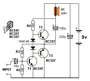
I have implemented the 3 transistor amplifier from "short circuits" magazine volume 1. It is almost identical to the circuit below but with the following component values changes:

R3 = 1k
R2 = 10k
R4 = 820R

Also the first 1N4148 is a 1N4004 in the short circuits version and the second 1N4148 is a 120R resistor.

I tried this but I ended up replacing it with a 'rubber diode' using a BC548 and a 20k pot.

The amplifier works but the sound from the speaker is so scratchy that you can't understand any lyrics etc.

Any suggestion on how I might improve the sound quality......just for fun.

Fig54aa.gif


Also are the following correct.

The 555 control pin is high impedance/resistance therefore it needs only a tiny current but reasonably high voltage levels to trigger it.
The class AB amplifier is responsible for amplifying current to drive lower impedance speakers therefore at higher power or db.
The class A amplifier is responsible for boosting either amplitude/voltage or current depending on how you bias it.
The previously suggested amplifier schematics are biased for amplitude/voltage boosting.
If you want to audio/pulse width modulate the 555 output then ideally you would want the duty cycle to be around 50%.

- - - Updated - - -

Actually playing around with this amplifier I found that leaving R3 at 1.5k and changing R2 to 3.9k improves the sound quality signficantly. So that would be increasing the voltage at the base of t1 wouldn't it from voltage divider principals? So what does this acheive re the complentary pair?

Just checked my voltage divider calculator and changing that resistor probably increases the voltage at the base of T1 to a little greater to what the rubber diode is probably biasing the complentary pair for (some where around 1V). So that would improve current flow through the pair and hence sound quality I guess.
 

Also are the following correct.

The 555 control pin is high impedance/resistance therefore it needs only a tiny current but reasonably high voltage levels to trigger it.
The class AB amplifier is responsible for amplifying current to drive lower impedance speakers therefore at higher power or db.
The class A amplifier is responsible for boosting either amplitude/voltage or current depending on how you bias it.
The previously suggested amplifier schematics are biased for amplitude/voltage boosting.
If you want to audio/pulse width modulate the 555 output then ideally you would want the duty cycle to be around 50%.
I can mostly agree.

You can "extract" a class A driver from the circuit, T1, R2-R4, input capacitor.
I din't hear an explanation about your intentions with feeding the audio signal to NE555 control input. If it's intended as simple PWM controller, you should consider the non-linear exponential RC waveform which translates into audio distortions.

My intention is to create a singing jacobs ladder. Actually I am intending to build an identical driver circuit and have stereo singing jacobs ladders. Don't know what effect a moving arc will have on the sound reproduction but I will find out.

I think I get the amplifier. The scratchyness is due to the fact that you are hearing only the peaks of the audio wave and therefore a very broken sound stream. Right?

That is due to the fact that the first stage class A amplifier is not outputing high enough voltage swing such that the second class ab stage only amplifies those parts of the peaks that produce enough of a voltage differnetial across the BE junctions. Correct?

So you adjust the class ab stage bias such that they are just on the verge of conducting and then you have to adjust the voltage swing on the class a first stage such that all parts of the audio signal are above the bias voltage for the second stage and all parts of the audio signal are amplified in current. Correct?

What would happen if you took the headphone output of a stereo, which is probably going to be for lower impedance / higher power head phones, in put it through a 555 control pin? Will this cause any damage to the 555 or whill the 555's high impedance just limit the current from the headphone output? Will this cause significant reduction in sound quality?
 

The class A gain is increased by the output stage bootstrap, but a there's no doubt that a class A output stage can achieve full output swing. You can find the calculation in most elementary electronics text books.
 

I changed R2 to 4.7k and fiddled around with my 'rubber diode' a bit and the sound volume increased signficantly and the sound quality was probably about as perfect as I am likely to get with the cheap speaker.

This is really exciting! My first fully working amplifier.

- - - Updated - - -

I connected my amplifier to a set of PC speakers and the sound quality is a bit better again.

After I finish with my singing jacobs ladder and tesla coil I might just have a bit more of a play with amplifiers.
 

Using "Transistor Amp" to design a common emitter amplifier for my 555 control pin. This software requires you specify an input impedance and an output impednce for the amplifier.
So can some one tell me the best value for these for the purpose of feeding an audio signal from a stereo head phone jack to the control pin of a 555.
 

Status
Not open for further replies.

Part and Inventory Search

Welcome to EDABoard.com

Sponsor

Back
Top