trav1s
Full Member level 1

I am new to Encounter RTL Compiler and I have created a simple circuit in Verilog in order to gain more understanding of the environment. The circuit is a 2-bit down-counter and this is the code used:
module down_counter(out, clk);
output [1:0] out;
input clk;
reg [1:0] out;
always @(posedge clk)
begin
out <= out - 1;
end
endmodule
The most optimal way to implement such a counter is by simply using two positive-edge DFFs, where each DFF is a bit of the counter (bit 0 and bit 1). Both DFFs use their own inverted output as D input. The bit 0 DFF recieves clk input from the external clock. The bit 1 DFF recieves clk input from the noninverted output of the bit 0 DFF. In short, it is not necessary to completely understand this paragraph; it is only important to know that the optimal design requires 2 DFFs and no additional logic.
However, this is not the result after logic synthesis in Encounter RTL Compiler.
My procedure has been as follows:
Set library attribute to a library containing a positive-edge DFF cell (dff_c2mosD)
Elaborate
Synthesize to generic
Synthesize to mapped
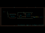
After synthesizing, even with a high effort level the following circuit is produced:

As you can see, instead of utilizing the inverting output of the DFF on the right, the compiler uses other logic to create the DFF input, requiring the extra XNOR gate. What is causing this extra logic? In other words, why is it not producing an optimal design?
Perhaps these details will help you with what the problem isn't. Here is what I have tried:
1. Using different libraries with different DFF definitions
2. Defining power and/or timing constraints before synthesis, including using an sdc file
3. Duplicating my proceedure on other machines
4. Using different designs, such as a DFF with asynchronous clear and preset
All efforts have failed to produce an optimal design in terms of timing, power, area or gate count, so I am looking forward to hearing from some of you experts about this. Shouldn't RTL compiler optimize for at least one of these factors by default?
module down_counter(out, clk);
output [1:0] out;
input clk;
reg [1:0] out;
always @(posedge clk)
begin
out <= out - 1;
end
endmodule
The most optimal way to implement such a counter is by simply using two positive-edge DFFs, where each DFF is a bit of the counter (bit 0 and bit 1). Both DFFs use their own inverted output as D input. The bit 0 DFF recieves clk input from the external clock. The bit 1 DFF recieves clk input from the noninverted output of the bit 0 DFF. In short, it is not necessary to completely understand this paragraph; it is only important to know that the optimal design requires 2 DFFs and no additional logic.
However, this is not the result after logic synthesis in Encounter RTL Compiler.
My procedure has been as follows:
Set library attribute to a library containing a positive-edge DFF cell (dff_c2mosD)
Elaborate
Synthesize to generic
Synthesize to mapped
After synthesizing, even with a high effort level the following circuit is produced:

As you can see, instead of utilizing the inverting output of the DFF on the right, the compiler uses other logic to create the DFF input, requiring the extra XNOR gate. What is causing this extra logic? In other words, why is it not producing an optimal design?
Perhaps these details will help you with what the problem isn't. Here is what I have tried:
1. Using different libraries with different DFF definitions
2. Defining power and/or timing constraints before synthesis, including using an sdc file
3. Duplicating my proceedure on other machines
4. Using different designs, such as a DFF with asynchronous clear and preset
All efforts have failed to produce an optimal design in terms of timing, power, area or gate count, so I am looking forward to hearing from some of you experts about this. Shouldn't RTL compiler optimize for at least one of these factors by default?


