circuit_hunter
Junior Member level 3

Hi
I am doing emcosimulation of an Rf rectifier.
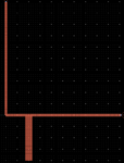
Please consider the following figure:

Part B contains the pads for diode and lumped components (boxed) plus an additional line. I EM cosimulated this , found the input impedance, and designed a matching network shown in Part A (boxed). I connect them (point 1 to point 2), and EM cosimulate it, gives decent performance with 60% peak efficiency. Please note that PART A is much bigger as compared to PART B, I have scaled its sybmol for clarity.
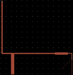
Now I make complete layout, drawing PART A and B in the same window as shown in the following figure:

I EM cosimulate this and efficiency is 3% !
The diode and lumped element and dimensions of each lines, everything are the same but still this poor performance is strange. Any idea why it would happen?
Thank you in advance for your precious time.
I am doing emcosimulation of an Rf rectifier.
Please consider the following figure:
Part B contains the pads for diode and lumped components (boxed) plus an additional line. I EM cosimulated this , found the input impedance, and designed a matching network shown in Part A (boxed). I connect them (point 1 to point 2), and EM cosimulate it, gives decent performance with 60% peak efficiency. Please note that PART A is much bigger as compared to PART B, I have scaled its sybmol for clarity.
Now I make complete layout, drawing PART A and B in the same window as shown in the following figure:

I EM cosimulate this and efficiency is 3% !
The diode and lumped element and dimensions of each lines, everything are the same but still this poor performance is strange. Any idea why it would happen?
Thank you in advance for your precious time.


