Lucast85
Member level 3

Hi everyone,
I'm going to drive a low side mosfet with a PWM signal with variable duty-cycle in the range 10%-100% but I see the duty-cycle is variable only in the range 99%-50% (see the video below).
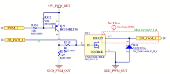
The frequency is 100Hz and the mosfet driver is an PNP so the pin PC9 (net PWM_1) of the microcontroller (STM32F407) is set to AF open drain. See the attached schematic.

When the uC pin pull to GND the pin PC9 (PWM_1), the external PNP and the power mosfet closes so the load is powered. When PWM_1 is open-drain, the PNP and the mosfet are off.
The timer3 clock is 20MHz, the prescaler is 2500 and the auto-reload-register is 100 so the PWM freq. is 100Hz. In the main loop I change the capture compare register (CCR) between 1 and 99 thus I expect to see a duty-cycle variable with the time in the range 1-99%.
From 99% to 50% seems ok but when the CCR is set below 50 (d.c. <50%) happened something courious. The waveform is the V_EB voltage of the PNP Q28.
It seems like if the uC try to drive the PNP with a mixed mode (push-pull from half period and t and with Open-drain from t and T). I'm sure that PC9 is configured as AF-OD with no internal pull-up and no pull-down resistors.
I'm going to drive a low side mosfet with a PWM signal with variable duty-cycle in the range 10%-100% but I see the duty-cycle is variable only in the range 99%-50% (see the video below).
The frequency is 100Hz and the mosfet driver is an PNP so the pin PC9 (net PWM_1) of the microcontroller (STM32F407) is set to AF open drain. See the attached schematic.

When the uC pin pull to GND the pin PC9 (PWM_1), the external PNP and the power mosfet closes so the load is powered. When PWM_1 is open-drain, the PNP and the mosfet are off.
The timer3 clock is 20MHz, the prescaler is 2500 and the auto-reload-register is 100 so the PWM freq. is 100Hz. In the main loop I change the capture compare register (CCR) between 1 and 99 thus I expect to see a duty-cycle variable with the time in the range 1-99%.
From 99% to 50% seems ok but when the CCR is set below 50 (d.c. <50%) happened something courious. The waveform is the V_EB voltage of the PNP Q28.
It seems like if the uC try to drive the PNP with a mixed mode (push-pull from half period and t and with Open-drain from t and T). I'm sure that PC9 is configured as AF-OD with no internal pull-up and no pull-down resistors.

