nadd
Member level 1

Hi everyone,
I'm trying to sample a 1MHz signal with the DMA method.
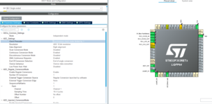
The settings that I use for ADC:
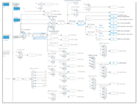
-Synchronous clock mode by 1 (72 MHz)
-12 Bits
-Continuous Conversion is enabled
-Sampling Time 19.5
The sampling rate is 72M/(19.5+12)= around 2.2M/s
The code is
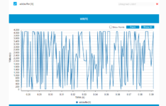
To read the data on the PC, I use STM32CubeMonitor. It allows max 4.6MHz for SWD protocol. But the result is not good for a 1MHz input sine signal, I guess the connection speed is not enough because, with the same settings, I can get clear results from the input signal until around 100Hz.
What can I do to get clear results?


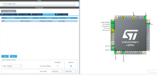
I'm also trying to use double buffer DMA and send it with the CDC_Transmit_FS command but I can't get rid of library issues. I added every path for the USB library, but it still finds an issue.
Is it a correct way or are there other methods that I can use?
I tried to copy the code that I'm working on it but the forum doesn't allow me to post it.
Briefly it is:
I'm trying to sample a 1MHz signal with the DMA method.
The settings that I use for ADC:
-Synchronous clock mode by 1 (72 MHz)
-12 Bits
-Continuous Conversion is enabled
-Sampling Time 19.5
The sampling rate is 72M/(19.5+12)= around 2.2M/s
The code is
C:
/* USER CODE BEGIN Header */
/**
  ******************************************************************************
  * @file           : main.c
  * @brief          : Main program body
  ******************************************************************************
  * @attention
  *
  * Copyright (c) 2023 STMicroelectronics.
  * All rights reserved.
  *
  * This software is licensed under terms that can be found in the LICENSE file
  * in the root directory of this software component.
  * If no LICENSE file comes with this software, it is provided AS-IS.
  *
  ******************************************************************************
  */
/* USER CODE END Header */
/* Includes ------------------------------------------------------------------*/
#include "main.h"

/* Private includes ----------------------------------------------------------*/
/* USER CODE BEGIN Includes */

/* USER CODE END Includes */

/* Private typedef -----------------------------------------------------------*/
/* USER CODE BEGIN PTD */

/* USER CODE END PTD */

/* Private define ------------------------------------------------------------*/
/* USER CODE BEGIN PD */
/* USER CODE END PD */

/* Private macro -------------------------------------------------------------*/
/* USER CODE BEGIN PM */

/* USER CODE END PM */

/* Private variables ---------------------------------------------------------*/
ADC_HandleTypeDef hadc1;
DMA_HandleTypeDef hdma_adc1;

UART_HandleTypeDef huart2;

/* USER CODE BEGIN PV */
int dma_value = 0;
uint16_t adcbuffer[1];
/* USER CODE END PV */

/* Private function prototypes -----------------------------------------------*/
void SystemClock_Config(void);
static void MX_GPIO_Init(void);
static void MX_DMA_Init(void);
static void MX_USART2_UART_Init(void);
static void MX_ADC1_Init(void);
/* USER CODE BEGIN PFP */

/* USER CODE END PFP */

/* Private user code ---------------------------------------------------------*/
/* USER CODE BEGIN 0 */
void HAL_ADC_ConvCpltCallback(ADC_HandleTypeDef* hadc) {
    if (hadc = &hadc1 ) {
        dma_value = adcbuffer[0] ;
    }
}
/* USER CODE END 0 */

/**
  * @brief  The application entry point.
  * @retval int
  */
int main(void)
{
  /* USER CODE BEGIN 1 */

  /* USER CODE END 1 */

  /* MCU Configuration--------------------------------------------------------*/

  /* Reset of all peripherals, Initializes the Flash interface and the Systick. */
  HAL_Init();

  /* USER CODE BEGIN Init */

  /* USER CODE END Init */

  /* Configure the system clock */
  SystemClock_Config();

  /* USER CODE BEGIN SysInit */

  /* USER CODE END SysInit */

  /* Initialize all configured peripherals */
  MX_GPIO_Init();
  MX_DMA_Init();
  MX_USART2_UART_Init();
  MX_ADC1_Init();
  /* USER CODE BEGIN 2 */
HAL_ADC_Start_DMA(&hadc1,adcbuffer,1);
  /* USER CODE END 2 */

  /* Infinite loop */
  /* USER CODE BEGIN WHILE */
  while (1)
  {
    /* USER CODE END WHILE */

    /* USER CODE BEGIN 3 */
  }
  /* USER CODE END 3 */
}

/**
  * @brief System Clock Configuration
  * @retval None
  */
void SystemClock_Config(void)
{
  RCC_OscInitTypeDef RCC_OscInitStruct = {0};
  RCC_ClkInitTypeDef RCC_ClkInitStruct = {0};
  RCC_PeriphCLKInitTypeDef PeriphClkInit = {0};

  /** Initializes the RCC Oscillators according to the specified parameters
  * in the RCC_OscInitTypeDef structure.
  */
  RCC_OscInitStruct.OscillatorType = RCC_OSCILLATORTYPE_HSI;
  RCC_OscInitStruct.HSIState = RCC_HSI_ON;
  RCC_OscInitStruct.HSICalibrationValue = RCC_HSICALIBRATION_DEFAULT;
  RCC_OscInitStruct.PLL.PLLState = RCC_PLL_ON;
  RCC_OscInitStruct.PLL.PLLSource = RCC_PLLSOURCE_HSI;
  RCC_OscInitStruct.PLL.PLLMUL = RCC_PLL_MUL9;
  RCC_OscInitStruct.PLL.PREDIV = RCC_PREDIV_DIV1;
  if (HAL_RCC_OscConfig(&RCC_OscInitStruct) != HAL_OK)
  {
    Error_Handler();
  }

  /** Initializes the CPU, AHB and APB buses clocks
  */
  RCC_ClkInitStruct.ClockType = RCC_CLOCKTYPE_HCLK|RCC_CLOCKTYPE_SYSCLK
                              |RCC_CLOCKTYPE_PCLK1|RCC_CLOCKTYPE_PCLK2;
  RCC_ClkInitStruct.SYSCLKSource = RCC_SYSCLKSOURCE_PLLCLK;
  RCC_ClkInitStruct.AHBCLKDivider = RCC_SYSCLK_DIV1;
  RCC_ClkInitStruct.APB1CLKDivider = RCC_HCLK_DIV2;
  RCC_ClkInitStruct.APB2CLKDivider = RCC_HCLK_DIV1;

  if (HAL_RCC_ClockConfig(&RCC_ClkInitStruct, FLASH_LATENCY_2) != HAL_OK)
  {
    Error_Handler();
  }
  PeriphClkInit.PeriphClockSelection = RCC_PERIPHCLK_USART2;
  PeriphClkInit.Usart2ClockSelection = RCC_USART2CLKSOURCE_SYSCLK;
  if (HAL_RCCEx_PeriphCLKConfig(&PeriphClkInit) != HAL_OK)
  {
    Error_Handler();
  }
}

/**
  * @brief ADC1 Initialization Function
  * @param None
  * @retval None
  */
static void MX_ADC1_Init(void)
{

  /* USER CODE BEGIN ADC1_Init 0 */

  /* USER CODE END ADC1_Init 0 */

  ADC_MultiModeTypeDef multimode = {0};
  ADC_ChannelConfTypeDef sConfig = {0};

  /* USER CODE BEGIN ADC1_Init 1 */

  /* USER CODE END ADC1_Init 1 */

  /** Common config
  */
  hadc1.Instance = ADC1;
  hadc1.Init.ClockPrescaler = ADC_CLOCK_SYNC_PCLK_DIV1;
  hadc1.Init.Resolution = ADC_RESOLUTION_12B;
  hadc1.Init.ScanConvMode = ADC_SCAN_DISABLE;
  hadc1.Init.ContinuousConvMode = ENABLE;
  hadc1.Init.DiscontinuousConvMode = DISABLE;
  hadc1.Init.ExternalTrigConvEdge = ADC_EXTERNALTRIGCONVEDGE_NONE;
  hadc1.Init.ExternalTrigConv = ADC_SOFTWARE_START;
  hadc1.Init.DataAlign = ADC_DATAALIGN_RIGHT;
  hadc1.Init.NbrOfConversion = 1;
  hadc1.Init.DMAContinuousRequests = ENABLE;
  hadc1.Init.EOCSelection = ADC_EOC_SINGLE_CONV;
  hadc1.Init.LowPowerAutoWait = DISABLE;
  hadc1.Init.Overrun = ADC_OVR_DATA_OVERWRITTEN;
  if (HAL_ADC_Init(&hadc1) != HAL_OK)
  {
    Error_Handler();
  }

  /** Configure the ADC multi-mode
  */
  multimode.Mode = ADC_MODE_INDEPENDENT;
  if (HAL_ADCEx_MultiModeConfigChannel(&hadc1, &multimode) != HAL_OK)
  {
    Error_Handler();
  }

  /** Configure Regular Channel
  */
  sConfig.Channel = ADC_CHANNEL_1;
  sConfig.Rank = ADC_REGULAR_RANK_1;
  sConfig.SingleDiff = ADC_SINGLE_ENDED;
  sConfig.SamplingTime = ADC_SAMPLETIME_19CYCLES_5;
  sConfig.OffsetNumber = ADC_OFFSET_NONE;
  sConfig.Offset = 0;
  if (HAL_ADC_ConfigChannel(&hadc1, &sConfig) != HAL_OK)
  {
    Error_Handler();
  }
  /* USER CODE BEGIN ADC1_Init 2 */

  /* USER CODE END ADC1_Init 2 */

}

/**
  * @brief USART2 Initialization Function
  * @param None
  * @retval None
  */
static void MX_USART2_UART_Init(void)
{

  /* USER CODE BEGIN USART2_Init 0 */

  /* USER CODE END USART2_Init 0 */

  /* USER CODE BEGIN USART2_Init 1 */

  /* USER CODE END USART2_Init 1 */
  huart2.Instance = USART2;
  huart2.Init.BaudRate = 38400;
  huart2.Init.WordLength = UART_WORDLENGTH_8B;
  huart2.Init.StopBits = UART_STOPBITS_1;
  huart2.Init.Parity = UART_PARITY_NONE;
  huart2.Init.Mode = UART_MODE_TX_RX;
  huart2.Init.HwFlowCtl = UART_HWCONTROL_NONE;
  huart2.Init.OverSampling = UART_OVERSAMPLING_16;
  huart2.Init.OneBitSampling = UART_ONE_BIT_SAMPLE_DISABLE;
  huart2.AdvancedInit.AdvFeatureInit = UART_ADVFEATURE_NO_INIT;
  if (HAL_UART_Init(&huart2) != HAL_OK)
  {
    Error_Handler();
  }
  /* USER CODE BEGIN USART2_Init 2 */

  /* USER CODE END USART2_Init 2 */

}

/**
  * Enable DMA controller clock
  */
static void MX_DMA_Init(void)
{

  /* DMA controller clock enable */
  __HAL_RCC_DMA1_CLK_ENABLE();

  /* DMA interrupt init */
  /* DMA1_Channel1_IRQn interrupt configuration */
  HAL_NVIC_SetPriority(DMA1_Channel1_IRQn, 0, 0);
  HAL_NVIC_EnableIRQ(DMA1_Channel1_IRQn);

}

/**
  * @brief GPIO Initialization Function
  * @param None
  * @retval None
  */
static void MX_GPIO_Init(void)
{
  GPIO_InitTypeDef GPIO_InitStruct = {0};

  /* GPIO Ports Clock Enable */
  __HAL_RCC_GPIOC_CLK_ENABLE();
  __HAL_RCC_GPIOF_CLK_ENABLE();
  __HAL_RCC_GPIOA_CLK_ENABLE();
  __HAL_RCC_GPIOB_CLK_ENABLE();

  /*Configure GPIO pin Output Level */
  HAL_GPIO_WritePin(LD2_GPIO_Port, LD2_Pin, GPIO_PIN_RESET);

  /*Configure GPIO pin : B1_Pin */
  GPIO_InitStruct.Pin = B1_Pin;
  GPIO_InitStruct.Mode = GPIO_MODE_IT_FALLING;
  GPIO_InitStruct.Pull = GPIO_NOPULL;
  HAL_GPIO_Init(B1_GPIO_Port, &GPIO_InitStruct);

  /*Configure GPIO pin : LD2_Pin */
  GPIO_InitStruct.Pin = LD2_Pin;
  GPIO_InitStruct.Mode = GPIO_MODE_OUTPUT_PP;
  GPIO_InitStruct.Pull = GPIO_NOPULL;
  GPIO_InitStruct.Speed = GPIO_SPEED_FREQ_LOW;
  HAL_GPIO_Init(LD2_GPIO_Port, &GPIO_InitStruct);

}

/* USER CODE BEGIN 4 */

/* USER CODE END 4 */

/**
  * @brief  This function is executed in case of error occurrence.
  * @retval None
  */
void Error_Handler(void)
{
  /* USER CODE BEGIN Error_Handler_Debug */
  /* User can add his own implementation to report the HAL error return state */
  __disable_irq();
  while (1)
  {
  }
  /* USER CODE END Error_Handler_Debug */
}

#ifdef  USE_FULL_ASSERT
/**
  * @brief  Reports the name of the source file and the source line number
  *         where the assert_param error has occurred.
  * @param  file: pointer to the source file name
  * @param  line: assert_param error line source number
  * @retval None
  */
void assert_failed(uint8_t *file, uint32_t line)
{
  /* USER CODE BEGIN 6 */
  /* User can add his own implementation to report the file name and line number,
     ex: printf("Wrong parameters value: file %s on line %d\r\n", file, line) */
  /* USER CODE END 6 */
}
#endif /* USE_FULL_ASSERT */What can I do to get clear results?


--- Updated ---
I'm also trying to use double buffer DMA and send it with the CDC_Transmit_FS command but I can't get rid of library issues. I added every path for the USB library, but it still finds an issue.
Is it a correct way or are there other methods that I can use?
I tried to copy the code that I'm working on it but the forum doesn't allow me to post it.
Briefly it is:
C:
#include "stm32f3xx_hal.h"
#include "usbd_cdc.h"

#define ADC_BUFFER_SIZE 128
uint16_t adc_buffer_1[ADC_BUFFER_SIZE];
uint16_t adc_buffer_2[ADC_BUFFER_SIZE];


  {
    // Start the ADC conversion and wait for completion
    if (HAL_ADC_Start_DMA(&hadc1, (uint32_t*)adc_buffer_1, ADC_BUFFER_SIZE) == HAL_OK)
    {
      // Wait for the ADC conversion to complete
      while (HAL_ADC_PollForConversion(&hadc1, 1000) != HAL_OK);

      // Start the USB transmission
      CDC_Transmit_FS((uint8_t*)adc_buffer_1, ADC_BUFFER_SIZE * 2);

      // Wait for the USB transmission to complete
      while (CDC_Transmit_FS((uint8_t*)adc_buffer_2, ADC_BUFFER_SIZE * 2) == USBD_BUSY) {};
    }
  }