Continue to Site

Welcome to EDAboard.com

Welcome to our site! EDAboard.com is an international Electronics Discussion Forum focused on EDA software, circuits, schematics, books, theory, papers, asic, pld, 8051, DSP, Network, RF, Analog Design, PCB, Service Manuals... and a whole lot more! To participate you need to register. Registration is free. Click here to register now.

STM32 and SPI Communication Issue

Status
Not open for further replies.

uranyumx

Advanced Member level 4
Full Member level 1
Joined
Mar 5, 2011
Messages
102
Helped
1
Reputation
2
Reaction score
0
Trophy points
1,296
Activity points
2,098
Hello,

I want to read data from a custom designed ADC chip through SPI interface. I guess there is an issue about my SPI codes, do you have any feedback on it?

SPI Baudrate: 10 Mbits/s, and the maximum SCLK frequency is 24 MHz

Codes in while loop:
Code:
uint16_t ReadADCAmplifier(uint8_t regAddress) {
  uint8_t txBuffer[2];
  uint8_t rxBuffer[2];
  txBuffer[0] = regAddress;
  txBuffer[1] = 0x00;
  HAL_GPIO_WritePin(ADCAmp_SPI2_CS_GPIO_Port, ADCAmp_SPI2_CS_Pin, GPIO_PIN_RESET);
  HAL_SPI_TransmitReceive(&hspi2, txBuffer, rxBuffer, 2, 1000);
  HAL_GPIO_WritePin(ADCAmp_SPI2_CS_GPIO_Port, ADCAmp_SPI2_CS_Pin, GPIO_PIN_SET);
  uint16_t value = ((rxBuffer[0] << 8) | rxBuffer[1]);
  return value;


SPI Settings:
Code:
static void MX_SPI2_Init(void)
{

  /* USER CODE BEGIN SPI2_Init 0 */

  /* USER CODE END SPI2_Init 0 */

  /* USER CODE BEGIN SPI2_Init 1 */

  /* USER CODE END SPI2_Init 1 */
  /* SPI2 parameter configuration*/
  hspi2.Instance = SPI2;
  hspi2.Init.Mode = SPI_MODE_MASTER;
  hspi2.Init.Direction = SPI_DIRECTION_2LINES;
  hspi2.Init.DataSize = SPI_DATASIZE_8BIT;
  hspi2.Init.CLKPolarity = SPI_POLARITY_LOW;
  hspi2.Init.CLKPhase = SPI_PHASE_2EDGE;
  hspi2.Init.NSS = SPI_NSS_SOFT;
  hspi2.Init.BaudRatePrescaler = SPI_BAUDRATEPRESCALER_4;
  hspi2.Init.FirstBit = SPI_FIRSTBIT_MSB;
  hspi2.Init.TIMode = SPI_TIMODE_DISABLE;
  hspi2.Init.CRCCalculation = SPI_CRCCALCULATION_DISABLE;
  hspi2.Init.CRCPolynomial = 10;
  if (HAL_SPI_Init(&hspi2) != HAL_OK)
  {
    Error_Handler();
  }
  /* USER CODE BEGIN SPI2_Init 2 */

  /* USER CODE END SPI2_Init 2 */

}
 

Attachments

  • 1678481773138.png
    1678481773138.png
    355.8 KB · Views: 137
  • 1678481840847.png
    1678481840847.png
    120.8 KB · Views: 131

Hi,

Error description is missing. Thus I didn't go deep into code.

One possible issue:
(rxBuffer[0] << 8)
Rxbuffer is 8 bits wide, thus if you shift it 8 bits left it might result in zero.
Better typecast it as 16bit value.

Klaus
 

Thank you for comments @KlausST !

I modified my codes like that,
Code:
uint8_t I_Read8(uint8_t I_address, uint8_t *I_data){

    uint8_t txIBuffer[2] = {(I_address | 0x80), 0x00};
    uint8_t rxIBuffer[2];

    HAL_GPIO_WritePin(I_SPI2_CS_GPIO_Port, I_SPI2_CS_Pin, GPIO_PIN_RESET);
    uint8_t status_I = (HAL_SPI_TransmitReceive(&hspi2, txIBuffer, rxIBuffer, 2, HAL_MAX_DELAY) == HAL_OK);
    HAL_GPIO_WritePin(I_SPI2_CS_GPIO_Port, I_SPI2_CS_Pin, GPIO_PIN_SET);

    *I_data = rxIBuffer[1];

    return status_I;

}

uint8_t I_Write8(uint8_t I_address, uint8_t I_data){

    uint8_t txIBuffer[2] = {I_address, I_data};

    HAL_GPIO_WritePin(I_SPI2_CS_GPIO_Port, I_SPI2_CS_Pin, GPIO_PIN_RESET);
    uint8_t status_I = (HAL_SPI_Transmit(&hspi2, txIBuffer, 2, HAL_MAX_DELAY) == HAL_OK);
    HAL_GPIO_WritePin(I_SPI2_CS_GPIO_Port, I_SPI2_CS_Pin, GPIO_PIN_SET);

    return status_I;

}

Then to make sure that it works, I call the chip ID which was in register 63

Code:
uint8_t I_data ;
I_Read8(63, &I_data);

      HAL_Delay(100);

Then, during the debug session, in the watch window, I got 'error, target not available' message.
--- Updated ---


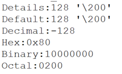
Update: I got a result which is the attached figure but it should be '2' in decimal based on the datasheet.
 

Attachments

  • 1678737050663.png
    1678737050663.png
    11.3 KB · Views: 117
Last edited:

Status
Not open for further replies.

Similar threads

Part and Inventory Search

Welcome to EDABoard.com

Sponsor

Back
Top