Continue to Site

Welcome to EDAboard.com

Welcome to our site! EDAboard.com is an international Electronics Discussion Forum focused on EDA software, circuits, schematics, books, theory, papers, asic, pld, 8051, DSP, Network, RF, Analog Design, PCB, Service Manuals... and a whole lot more! To participate you need to register. Registration is free. Click here to register now.

Stable Arduino Quadcopter with 30 min flight time

Status
Not open for further replies.

jaosef

Newbie level 4
Newbie level 4
Joined
Apr 22, 2015
Messages
6
Helped
0
Reputation
0
Reaction score
0
Trophy points
1
Activity points
44
Hi, I've built a home made Arduino Quadcopter and made a video log of the build. The fligt time is about 30 minutes and the motor-to-motor size is about 152".
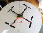
quad_small.jpg
Enjoy!
https://www.youtube.com/watch?v=xUMeya-8dFQ
 

30 minutes is very impressive!

What's the weight of the vehicle?
What's the motor's Kv rating?
What's the propeller diameter?
What's the battery capacity and voltage?
 

30 minutes is very impressive!

What's the weight of the vehicle?
What's the motor's Kv rating?
What's the propeller diameter?
What's the battery capacity and voltage?

Thank you, all the anwsers to your questions can be found in the video + description.
But to give som quick anwsers:
Weight: 1054g
Motor kv rating: 1200
Prop diam: 10"
Battery capacity (total): 7400mAh @3s
 

Do you use PID control for stabilization ?
Or something else ?
 

Do you use PID control for stabilization ?
Or something else ?

Yes, I use PID-control.

I set the terms as:
Code:
Px = (wanted_x_angle-current_x_angle)*kp
Ix = Ix + (wanted_x_angle-current_x_angle)*dt*ki
Dx = x_angle_rate*kd

I do this for the x,y and z-angle.
 
Last edited by a moderator:

And what is the formula behind the angle setting?
 

And what is the formula behind the angle setting?

The x, and y-angle are calculated by using the component of the gravitational force in each direction (this is measured by the accelerometer). That comes down to the expression:
x_angle=atan(x_component/sqrt(y_component^2+z_component^2))
y_angle=atan(y_component/sqrt(x_component^2+z_component^2))

The z- angle (yaw) has to be calculated by integrating the rate of change of the z-angle. This is because the acceleromter cannot measure changes to the z-angle (you need a magnetometer for this), so what you do is you integrate the z-angle velocity given by the gyro. It simply comes down to the expression:
z_angle = z_angle + z_angle_rate*dt

These angles are then plugged in to the PID-regulation (for the P and I term as described in my last post), and for the D-term you only use the angle-rate of change (deg/s).

I hope this made sense.
 

Yes, it's clear.
For the inclination reading, did you use a simple IMU? Or something that does sensor fusion?
 

Yes, it's clear.
For the inclination reading, did you use a simple IMU? Or something that does sensor fusion?
Yes, I use a MPU6050, that is an IMU with both accelerometer and gyro.
I use data from both the accelerometer and gyro in the filter to get less noise and better accuracy in the angle-estimates.
 

Status
Not open for further replies.

Similar threads

Part and Inventory Search

Welcome to EDABoard.com

Sponsor

Back
Top