Vermes
Advanced Member level 4

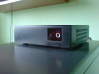
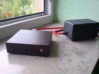
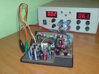
It is a DAC USB based on PCM2702 and built in headphones amplifier on TPA6120.
Sound:
To create described here devices, first step should be testing and building a converter powered from USB. Then, add a power supply and filter. The sound card should play like a good quality CD player.
Construction:
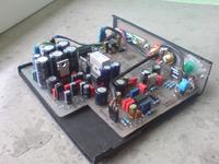
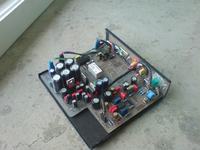
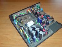
All the PCB were made in thermal transfer method and protected by a solution of rosin. The system can be divided into four parts:
- converter PCM2702 with filter
- headphones amplifier
- headphones amplifier switch
- power supply
There are also transformers and mains filters in the second housing.
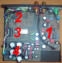
Converter PCM2702:
DAC is a modified avt design made of PCM2702. Digital and analog parts are powered from separate transformers, and their grounds are connected in one point. There is a filter on operational amplifier, which eliminates the noise produced during converting C/A. The operational amplifier is OPA2134. It is symmetrically powered +/-15V, all resistors 1% metalized, capacitors mainly WIMA and Panasonic FC, Nichicon at the output Converter is connected to additional USB controller in a computer (port PCI) – it provides stability.
Headphones amplifier:
It can be TPA6120 in a typical application with buffer on AD8066, but you can use only operational amplifier as well (LM4562). Board is designed so that the output is after WO and TPA, and places for capacitors are double. The amplifier is powered from the same voltage as the filter on OPA2134. Resistors 1% metalized, output capacitors Nichicon 10uF.
Headphones amplifier switch:
Normally, the headphones amplifier is off. It is activated by a microswitch on front panel, which controls the switch based on a relay and CD4069. Filter is permanently on and the swtich operates only as the amplifier switch.
Power supply:
The power supply provides 5 voltages: from the first transformer 3,3V for digital part and 5V for the headphones amplifier switch, and from the second 5V for analog part and +/-15V for the filter and headphones amplifier. Other components used for this device are: BYV27 diodes in the bridges, filtering capacitors are mainly Rubycon ZL and Wima and Nippon with Panasonic FC, stabilizers LM317/337, 2x Lm7805.Two transformers with filter and placed in a separate housing, connected by a cable. DB9 (COM) is used as a temporary socket.
Pictures:
Link to original thread (useful attachment) - Karta dźwiękowa/DAC PCM2702 + TPA6120