Vermes
Advanced Member level 4

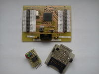
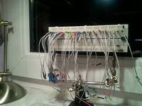
It is an useful device to connect prototypes of the circuits or simple circuits for education/training. A main advantage of this method is its greater flexibility than with a start board, although the second method requires less time.
The first module is used for SD cards.
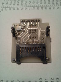
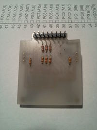
It contains a card slot, stabilizer 3,3V Low Drop, power signalization, data lines voltage dividers (microcontrollers used are adapted to 5V power supply) and the possibility of rising to +Vcc or mass of the switches outputs the write-protect and the card in the slot.
Another module is the board with microcontroller Atmega128.
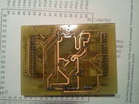
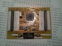
It is a simple construction with microcontroller, supply stabilizer, programmer slot in KANDA standard, reset button, supply signalization, jumpers to configure the microcontroller power supply and reference voltage source and the outputs of all the IO ports. There is also a stand that allows rapid exchange of the quartz resonator. There are three ways to power it: directly from the programmer, from an external non-stabilized power supply 7-30V, or from an external source of stabilized voltage 5V.
The third module is the board with the RTC system PCF8583
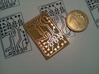
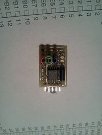
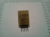
It contains the RTC system and all elements required for its proper work: quartz, filtering capacitors, resistors that pull-up I2C lines and interrupt to +Vcc together with jumpers that enable separation of the pull-up. There is also signalization of the supply and interrupt on the pin INT of the system – useful when PCF alarm register is used, it simply blinks in normal mode.
The board with the microcontroller allows for convenient use of the system in the housing TQFP64, its smooth programming and very flexible capabilities of use in different applications.
The whole is finished with a set of connecting cables and connectors to the contact plate, all DIY.
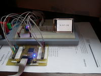
A sample of two modules used together:
Link to original thread (useful attachment) – Kilka przydatnych modułów do łączenia układów testowych