Nysix
Junior Member level 2

Hi all 
I'm still having problems with my inverter circuit. Looking for informations about circuits and IR2110, I designed the following circuit:

My goal is control a AC motor changing its velocity, keeping the relation Voltage/Frequency be constant. The desired inverter's output is:

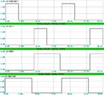
I'm using a 16F877A for generate the switching signal (four signals, one to each IGBT). Works fine on ISIS, but when I assembled this circuit in protoboard, it don't work. I'm no sure about what is not working properly...
- The IR2110 works in this frequency interval (5~60 HZ)?
- Vdd pin should be connected in +5V source and Vss in common ground circuit?
- The bootstrap capacitor is correct (330uF) for my application?
Thanks for any help and sorry for my english :/
I'm still having problems with my inverter circuit. Looking for informations about circuits and IR2110, I designed the following circuit:

My goal is control a AC motor changing its velocity, keeping the relation Voltage/Frequency be constant. The desired inverter's output is:

I'm using a 16F877A for generate the switching signal (four signals, one to each IGBT). Works fine on ISIS, but when I assembled this circuit in protoboard, it don't work. I'm no sure about what is not working properly...
- The IR2110 works in this frequency interval (5~60 HZ)?
- Vdd pin should be connected in +5V source and Vss in common ground circuit?
- The bootstrap capacitor is correct (330uF) for my application?
Thanks for any help and sorry for my english :/


