Continue to Site

Welcome to EDAboard.com

Welcome to our site! EDAboard.com is an international Electronics Discussion Forum focused on EDA software, circuits, schematics, books, theory, papers, asic, pld, 8051, DSP, Network, RF, Analog Design, PCB, Service Manuals... and a whole lot more! To participate you need to register. Registration is free. Click here to register now.

[SOLVED] Soldering problems - pls help !!

Status
Not open for further replies.

tronix_geek

Newbie level 3
Newbie level 3
Joined
Aug 19, 2012
Messages
3
Helped
0
Reputation
0
Reaction score
0
Trophy points
1,281
Activity points
1,314
Dear all,

I am new to this forum. Please forgive me if my doubt is tooo basic. I have none else to ask .

I am attaching two pics of the board i bought for soldering resistors , transistors etc. I am learning to solder now. I have attached both faces of the board - Soldering face & Component attaching face.

Soldering Face
Soldering face.jpg


Component attaching face

Component attaching face.jpg


In my Board, the dots are not interconnected , like in a Bread Board.


My doubt is this :

I dont know how to connect one lead each of 2 resistors together on this board. Let the leads of resistor R1 go into the dots A & B & let the leads of resistor R2 go into dots C & D. After successfully soldering R1 & R2 on to the board, now i have to connect a copper cable between dots B & C for R1 & R2 to be in series.

Is it enough f i melt the solidified solder at dot B & immediately attach the cable there. Will the connection be strong ? I hold soldering iron in my right hand & the copper cable in my left -How do i apply more solder at that dot ? I simply don't get it.


Please Help me !!
 

Part of soldering is making a three hand operation with two hands...

You should melt the solder on the soldering post so that the solder flux clears the area to get a proper joint, if you just add solder on the iron tip and transfer in in on the PCB it will not work.
Search in youtube, there are a lot of videos.

There are many kind of boards, maybe board like the following would be more convenient.

PROTO777.jpg

STPBRD2.jpg

Alex
 

This looks like a PC prototyping card with an ISA connector, the kind used in older PCs.

Some boards have the pads joined in strips but on that type you have to "join the dots" manually. What you have is basically a method of mounting the components but you have to link the connections yourself.
Soldering is something you just have to learn by experimenting but the principle is to first flow some solder on the pad, then flow some solder onto the wire so boith are ready to join and have enough solder between them to make a good connection. Then with the board lying down, solder side facing up, apply the iron in one hand and the wire in the other, place the wire over the pad and then touch it with the iron to flow the solder. Don't be afraid of applying too much heat, the solder should fully melt and flow around the wire.

It takes practise but after a while it becomes second nature. Mind you, I've seen people who have worked in the industry all their lives who still can't solder properly :|

Brian.
 

Is it enough f i melt the solidified solder at dot B & immediately attach the cable there. Will the connection be strong ? I hold soldering iron in my right hand & the copper cable in my left -How do i apply more solder at that dot ? I simply don't get it.
First tin the end of the wire. This means to melt some solder on it, so the end of the wire is covered with some solder.

Now put the end of the wire onto the copper dot and push down on it with the soldering iron. The solder on the wire and the solder on the copper will melt together and make a good joint.
 

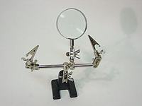
You can also buy or make a "third hand" solder helper, to help hold components or wires while you solder them.

 
Part of soldering is making a three hand operation with two hands...

You should melt the solder on the soldering post so that the solder flux clears the area to get a proper joint, if you just add solder on the iron tip and transfer in in on the PCB it will not work.
Search in youtube, there are a lot of videos.

There are many kind of boards, maybe board like the following would be more convenient.

View attachment 78913

View attachment 78914

Alex

The first picture posted by you - What do you call such a board as ? It looks like a bread board !! That would work perfect for me , I CAN solder comfortably on that , i feel because no need of extra wires to connect components in series.

I stay in India. I don't whether i could get them here..
 

I'm not sure how they are called, they are just pics I got from a Thailand eshop.

I guess you should search for a protoboard with stripes or pads
 

I'm not sure how they are called, they are just pics I got from a Thailand eshop.

I guess you should search for a protoboard with stripes or pads

Tx Alex !!

I also thank everyone for their reply. The video on soldering was sooooooperb !! Tx a lot dear.

I also found out that the pics i posted were that of MATRIX BOARD.. Just finished soldering 3 resistors & LED in series successfully on that shitty matrix board..

Got to go hunting for boards with interconnected points . Tx all !!

- - - Updated - - -

That is GP board (general purpose) PC prototype board.

wow !! Tx Bala !! Saw ur reply only now !! ;)

GP Board - Don't know whether i wud get it in this part of India .. lemme c..
 

wow !! Tx Bala !! Saw ur reply only now !! ;)

GP Board - Don't know whether i wud get it in this part of India .. lemme c..

i dono that but you can always try it online i am sure it is available online
 

Status
Not open for further replies.

Part and Inventory Search

Welcome to EDABoard.com

Sponsor

Back
Top