Continue to Site

Welcome to EDAboard.com

Welcome to our site! EDAboard.com is an international Electronics Discussion Forum focused on EDA software, circuits, schematics, books, theory, papers, asic, pld, 8051, DSP, Network, RF, Analog Design, PCB, Service Manuals... and a whole lot more! To participate you need to register. Registration is free. Click here to register now.

Software controlled DI Box project.

Status
Not open for further replies.

Dismantle.Repair

Newbie level 3
Newbie level 3
Joined
Dec 14, 2011
Messages
3
Helped
0
Reputation
0
Reaction score
0
Trophy points
1,281
Activity points
1,307
Hi everyone,

This is my first post! (This is also my first real project for college)

The aim of this project is to write a piece of software that controls an Arduino and in turn control various DI Box switches.

I've de-soldered the first switch and the logic is as follows:

SwitchOpen.jpg

SwitchClosed.jpg

OveridingSwitch.jpg

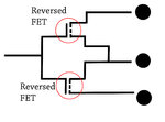
I wondered if it would be possible to use a logic n-MOSFET and a logic p-MOSFET to make the connections. (Obviously the same system would need to be employed on the left and right hand side) - This way one logic 5V signal from an Arduino would supposedly make these connections.

At the same time I was recommended by another person that a DPDT relay switch would be a good solution.

Any advice/comment on which is the best solution would be extremely helpful.
 

Given the low signal levels within a DI box, you will find a definite advantage in using relays with gold plated contacts for your switching. Solid state switches will contribute significant noise degradation to these low level signals.

hope this assists
Mik
 
Thanks very much MIK.

I should've mentioned that the specific switch is the -20dB pad. (I'm not sure if the audio actually goes through this switch or if it's just logic?)

What I'm not sure is how to choose a relay type and also how to connect it to the digital logic outputs from an Arduino board? - would a logic MOSFET still be required?

Thanks
 

The 20dB pad for DI boxes is normally in the Audio signal path at the input to the circuitry.

For interfacing a relay to your processor logic outputs, any suitable buffer such as the 'logic MOSFET' you suggest will be able to drive a relay.... check the relay coil current/voltage for suitable types.

Have a look at this sealed relay as a possible one to use: Buy Electromechanical Relays DPCO subminiature relay,3A 12Vdc coil,BP TE Connectivity V23105A5476A201 online from RS for next day delivery.
Other coil voltages are available depending on what power supply you have available.
Don't forget to fit a back EMF diode across your relay coil!
Mik
 
Last edited:
Fantastic thanks so much for your help. (This forum's great!)

Out of interest what does the EMF diode do? - At a guess stop the board getting fried if there's a problem?

The specific box is a Behringer GI100 (Cheap n' cheerful) so the power supply is a 9V battery. - How do you match the coil up, is it supposed to be the same at the power supply?

Do you know of any good beginners tutorials to relays, as I'm not quite sure where to start?

Thanks once again.
 

as a starting point for Relays try: Relay - Wikipedia, the free encyclopedia

For an Inductor, the relay coil in this case; it holds a stored Magnetic charge in it's core when energised. When you switch the relay coil off the stored charge has to go somewhere so instead of leaving it to generally try to dissipate through the drive circuitry a diode is used to conduct it safely away. (a bit oversimplified!)

Mik

---------- Post added at 16:08 ---------- Previous post was at 16:01 ----------

Re: "The specific box is a Behringer GI100 (Cheap n' cheerful) so the power supply is a 9V battery. - How do you match the coil up, is it supposed to be the same at the power supply?"

seem to think for these that Batteries are used. The Relay current will cause battery life to be reduced so have a look at 'Latching' relay types.
Coil Voltage you'll see from Relay Spec sheets is over a range of Voltages. You will have a Voltage drop with your switching transistor so look at 6Volt coil types for your 9Volt supply - although these will draw more current.
Best option is to use the DC supply from your controller as the relay coil is completely isolated from it's contacts, then leaving a seperate 'clean' supply for your Audio path.
Mik
 

Status
Not open for further replies.

Part and Inventory Search

Welcome to EDABoard.com

Sponsor

Back
Top