amitjagtap
Full Member level 5

hi all,
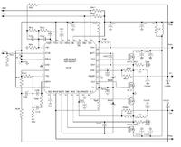
I m using dual DC to DC converter chip from Analog devices ADP1829.
The schematic and other details are given in pdf attached.

I need to know whether snubber circuit is required for switching MOSFETs or not?
If RC snubber is required. then How I can decide values of R & C before implementing the complete DC to DC circuit on the board (Board which includes Processor,FPGA and other chips). I mean to PCB is not yet ready for all these, so i can't implement this circut and follow the traditional way to decide RC by observing the switching waveform for its damped frequency.
Also, I need to know which type of components R & C are recommended for snubber. For example: ceramic or tantalum cap. and wire wound or metal film resistor, what will be the wattage required etc.
Experts please give their comments. [/b]
I m using dual DC to DC converter chip from Analog devices ADP1829.
The schematic and other details are given in pdf attached.

I need to know whether snubber circuit is required for switching MOSFETs or not?
If RC snubber is required. then How I can decide values of R & C before implementing the complete DC to DC circuit on the board (Board which includes Processor,FPGA and other chips). I mean to PCB is not yet ready for all these, so i can't implement this circut and follow the traditional way to decide RC by observing the switching waveform for its damped frequency.
Also, I need to know which type of components R & C are recommended for snubber. For example: ceramic or tantalum cap. and wire wound or metal film resistor, what will be the wattage required etc.
Experts please give their comments. [/b]