cupoftea
Advanced Member level 6

Hi,
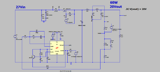
The attached is a 60W, 420kHz Buck with a secondary LC filter after the Buck stage.
The Buck had a crossover frequency of 1700Hz before the LC post filter was added.
The post filter is 1uH and 20mF...so a resonant freq of 1130Hz. This is less than the
aforementioned crossover frequency, but it does not make for instability. (as the LTspice sim shows)
Interestingly , at startup, the Buck's output shows a decaying oscillation of some 50Hz.
Where does the frequency come from?
This in fact shows the way forward for high frequency DCDC current mode Bucks.....ie, just use a tiny ceramic output
capacitor bank, and a small output inductor...and whatever input capacitance that the load has , it wont make for instability.
So this is obviously how you can save money on output filter capacitors. There's simply no need for them...as this shows.
It wont go unstable almost no matter how much extra capacitance is added at the output...even with a series L filter inductor.
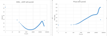
...Look at the way that, after the LC filter is added, that the Magnitude bode plot no longer crosses over at any sane frequency....and yet the ltspice sim still shows stability.
So why do all application notes all show huge el caps on the output of dcdc's? (ok for transient response but often that isn't necessary,
and even then , the load equipment is likely to have its own input capacitance anyway)
pg 10 shows how to adjust bode calc for post LC filter...
Attachments
Last edited:


