SMPS transformer design issue
- Thread starter satiz
- Start date
- Status
- Not open for further replies.

- Joined
- Apr 1, 2011
- Messages
- 15,820
- Helped
- 2,918
- Reputation
- 5,850
- Reaction score
- 3,075
- Trophy points
- 1,393
- Location
- Minneapolis, Minnesota, USA
- Activity points
- 118,468
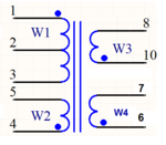
Your secondaries have the same number of turns (9T). Theory says they produce the same voltage. However your specs say you want three different voltages. Does the transformer have internal construction which provides this? Or did you intend to add regulation?
satiz
Member level 5

Your secondaries have the same number of turns (9T). Theory says they produce the same voltage. However your specs say you want three different voltages. Does the transformer have internal construction which provides this? Or did you intend to add regulation?
Hi Thanks for your reply,
Could you give my some reference guide for transformer design.
c_mitra
Advanced Member level 6
Because you will have difficulty to wind a fractional turn, you can keep the number of turns same for 5V and 6V and use twice the number of turns for the 12V coil. You have not mentioned the current requirement (loads) but it may be simpler to use bifilar and /or trifilar windings in case you need higher currents.
Your input is close to 50V?
Your input is close to 50V?
satiz
Member level 5
Because you will have difficulty to wind a fractional turn, you can keep the number of turns same for 5V and 6V and use twice the number of turns for the 12V coil. You have not mentioned the current requirement (loads) but it may be simpler to use bifilar and /or trifilar windings in case you need higher currents.
Your input is close to 50V?
My input is 230V AC, 50Hz.
I tried with PI expert, But the thing is I need 5KVA Isolation between the outputs 5,12 and 15. I don't know how to get Isolated output design in PI expert.
- - - Updated - - -
you can use PI Expert for the design
How can we get isolated output using PI expert please guide me
smijesh
Advanced Member level 1
Please specify the power or output current requirement, For this TNY switch can deliver 20W
Transformer design step in (PI expert or other tool)
Select transformer (E20 or E25)
Calculate required air gap
Calculate no of turns - primary and secondary
Wire thickness primary(25AWG to 32AWG)
Wire thickness for secondary
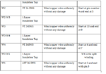
For 5K isolation use polyester yellow tape in between winding
For 5K isolation use big bobbin or bobbin having more length between primary to secondary(Crepage)
See similar TOP Switch transformer design
satiz
Member level 5
Please specify the power or output current requirement, For this TNY switch can deliver 20W
Transformer design step in (PI expert or other tool)
Select transformer (E20 or E25)
Calculate required air gap
Calculate no of turns - primary and secondary
Wire thickness primary(25AWG to 32AWG)
Wire thickness for secondary
For 5K isolation use polyester yellow tape in between winding
For 5K isolation use big bobbin or bobbin having more length between primary to secondary(Crepage)
See similar TOP Switch transformer design
Hi Thanks for your reply,
I need the following power specifications
12V*1 Amps =12W
6V*.5Amps =3W
15V*.25Amps=3.75W
------------------------------
Total power =18.75W
------------------------------
I need procedure to calculated the secondary winding ? is there any formula available ?
- - - Updated - - -
Hi All I have one more doubt,
In my design I placed the common mode choke before the rectifier, But in PI expert t design common mode choke is placed after the bridge rectifier.
What is the difference and which one is more effective ? Any one explain in detail please.
smijesh
Advanced Member level 1
L primary = Vin*Ton/I pk Ipk = 5.5*I in
Primary turns Np = √(L primary/Al Vlue of the core )
Secondary – 1 turns(Ns-1) = Npri(Vout -1+Vd)*(1-Dmax) /Vin Dmax
(Vd diode voltage drop , D max Duty cycle )
Secondary – 2 turns(Ns-2) = (Vsec -2 + Vd)*Ns-1 /(Vsec -1 + Vd)
Secondary – 3 turns(Ns-2) = (Vsec -3 + Vd)*Ns-1 /(Vsec -1 + Vd)
Primary
18/230= 100mA
(30AWG copper wire)
12V*1 Amps =12W (20AWG copper wire)
6V*.5Amps =3W (24AWG copper wire)
15V*.25Amps=3.75W (26AWG copper wire)
Hope it is helpful
satiz
Member level 5
L primary = Vin*Ton/I pk Ipk = 5.5*I in
Primary turns Np = √(L primary/Al Vlue of the core )
Secondary – 1 turns(Ns-1) = Npri(Vout -1+Vd)*(1-Dmax) /Vin Dmax
(Vd diode voltage drop , D max Duty cycle )
Secondary – 2 turns(Ns-2) = (Vsec -2 + Vd)*Ns-1 /(Vsec -1 + Vd)
Secondary – 3 turns(Ns-2) = (Vsec -3 + Vd)*Ns-1 /(Vsec -1 + Vd)
Primary
18/230= 100mA
(30AWG copper wire)
12V*1 Amps =12W (20AWG copper wire)
6V*.5Amps =3W (24AWG copper wire)
15V*.25Amps=3.75W (26AWG copper wire)
Hope it is helpful
Hi,
I Need more clarity on the above equation. Could you explain me with one example ? It will be very helpful to me
schmitt trigger
Advanced Member level 5
What is exactly that you don't understand from a simple algebraic equations?
a) Define primary inductance based on the requirements
b) Calculate primary turns based on the primary inductance
c) Calculate the main secondary turns based on primary turns and requirements
d) calculate the auxiliary secondaries based on the main secondary and requirements.
a) Define primary inductance based on the requirements
b) Calculate primary turns based on the primary inductance
c) Calculate the main secondary turns based on primary turns and requirements
d) calculate the auxiliary secondaries based on the main secondary and requirements.
- Status
- Not open for further replies.
Similar threads
-
Solder mask bridge issue
- Started by Eyal78
- Replies: 1
-
Help with 4-20mA System XTR116: AD623 Offset Issue at 0mV Input
- Started by kemaltekbas
- Replies: 3
-
PCB Layout Displaying White Screen Issue
- Started by victor-anthony
- Replies: 2
-
Unrouted net issue when design rule check in Altium
- Started by cupoftea
- Replies: 0
-
Cost estimation of PCB design
- Started by engr_joni_ee
- Replies: 3


