Vermes
Advanced Member level 4

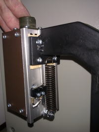
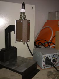
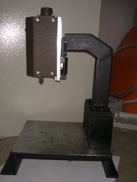
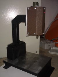
It is a small dril for laminate and other soft materials. Assumption of this construction was to create the cheap and useful device.
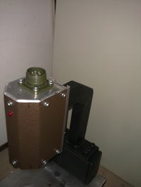
Spindle was made of respectively bent 2mm thick aluminum sheet. The front cover is 0,5mm thick processing metal sheet. The whole after assembly is quite rigid. The engine was taken from 12V Bosh cordless. On the psindle axis, there was mounted a mini drill chuck 0,5-6mm. Z shift rails were made of two 120mm pieces of rails with „forks” of plastic.
Frame and base were made of steel, so they are solid and do not tremble.
Supply is a rectifier made of 72A 13,5V transformer and 25A rectifier bridge. Housing was taken from a broken computer power supply. There is a microswitch in the rear of the spindle, which causes turning on the rotations of the spindle to shift -Z.
Pictures:
Link to original thread (useful attachment) - Wiertarka do płytek PCB