Continue to Site

Welcome to EDAboard.com

Welcome to our site! EDAboard.com is an international Electronics Discussion Forum focused on EDA software, circuits, schematics, books, theory, papers, asic, pld, 8051, DSP, Network, RF, Analog Design, PCB, Service Manuals... and a whole lot more! To participate you need to register. Registration is free. Click here to register now.

Slowing 555 oscillator frequency over time

Status
Not open for further replies.

ahahn

Newbie level 3
Newbie level 3
Joined
Sep 13, 2012
Messages
3
Helped
0
Reputation
0
Reaction score
0
Trophy points
1,281
Activity points
1,315
Hi,
I want to slowly decrease the frequency of a 555 astable oscillator over time, until it reaches a certain end frequency. The oscillator should start at a particular frequency but the frequency can start decreasing as soon as the timer is powered on.

My initial thought was to use the 555's control pin. By charging a capacitor through a resistor, I could increase the voltage at the pin. Unfortunately, the internal voltage divider (5k/10k ohms) is too low impedance for the R value needed to charge the capacitor (1M-10M ohms). So I tried using an LM317 to generate a voltage at the control pin, while slowly increasing the LM317 voltage with a soft start circuit (**broken link removed**). Unfortunately the LM317 doesn't get over 1.9V this way. (Transistor is a BC327 instead of the 2N2907, Vsupply is 9V, the capacitor is 10uF, the resistor R3 from the soft start schematic is 470k).

Any ideas how I could do this? Eventually I want to make the 555 take twenty or thirty minutes to reach the final frequency.
 

You want to pull the 555 control pin low, then raise it gradually. The 555 has an internal network of 5K resistors. To overcome their effect, your device needs a low impedance.

You have a slowly charging capacitor which will provide the control signal. However its charging resistor is high impedance.

You need something to go in between the two.

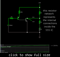
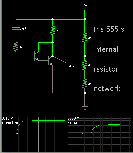
A pair of transistors may do the trick.

Schematic:


You may want to alter the output's beginning and end levels. This may be possible with another resistor or two.

The timeframe is 10 seconds using a .1 uF capacitor. By substituting a 10 uF, it will extend the timeframe to 1,000 seconds.

Not shown is a way to discharge the capacitor. This will take some more work. It may turn out to be easier to charge the capacitor at the beginning, then let it discharge.
 
You will always struggle with long time constants using simple circuits due to capacitor leakage. Long time delays are therefore usually made using higher frequencies and counters/microcontrollers.

Keith.
 

The 555 is a good timer but a poor RC oscillator. It is not worth time to select stable R and C to improve its stability. You could use it with only 3Vcc to prevent heating .For stable frequency source, select a quartz oscillator at e.g.10 kHz, then use TTL dividers to get your frequency. A 74HC390 can divide by two, five and ten, etc.
 
  • Like
Reactions: ahahn

    ahahn

    Points: 2
    Helpful Answer Positive Rating
You have a slowly charging capacitor which will provide the control signal. However its charging resistor is high impedance.

You need something to go in between the two.

A pair of transistors may do the trick.

Schematic:


You may want to alter the output's beginning and end levels. This may be possible with another resistor or two.

The timeframe is 10 seconds using a .1 uF capacitor. By substituting a 10 uF, it will extend the timeframe to 1,000 seconds.


Thanks! It looks like I could substitute in a Darlington transistor too. Where is the current coming from to charge the capacitor through the 1M resistor? Most datasheets don't specify a collector-base leakage current (or voltage), I didn't realize there was one.

[Edit: never mind, I didn't notice there were four connections to the two transistors instead of the three a Darlington pair would give.]
 

I'm glad you have also taken into account the capacitor leakage current.

Keith
 

Thanks! It looks like I could substitute in a Darlington transistor too. Where is the current coming from to charge the capacitor through the 1M resistor? Most datasheets don't specify a collector-base leakage current (or voltage), I didn't realize there was one.

[Edit: never mind, I didn't notice there were four connections to the two transistors instead of the three a Darlington pair would give.]

Yes, the PNP conducts from the emitter (upper terminal) out through the base, to charge the capacitor.

The schematic above has a Sziklai pair, not too different from the darlington concept.

I did try an NPN darlington arrangement and it worked okay, although the charging curve was faster.

28_1347659171.png


So you get the idea. You can try various configurations and see what suits your purpose.
 
You want to pull the 555 control pin low, then raise it gradually. The 555 has an internal network of 5K resistors. To overcome their effect, your device needs a low impedance.

You have a slowly charging capacitor which will provide the control signal. However its charging resistor is high impedance.

You need something to go in between the two.

A pair of transistors may do the trick.

Schematic:


You may want to alter the output's beginning and end levels. This may be possible with another resistor or two.

The timeframe is 10 seconds using a .1 uF capacitor. By substituting a 10 uF, it will extend the timeframe to 1,000 seconds.

Not shown is a way to discharge the capacitor. This will take some more work. It may turn out to be easier to charge the capacitor at the beginning, then let it discharge.

Your time figures are a bit off, and the reaction is the inverse of what I'm looking for. Using a 0.1uF capacitor the timeframe is more on the order of a minute.

Over time the 555 output also changes from a sparse pulse waveform to a higher-frequency square wave. This may however be due to the way I have the 555 configured (instead of the standard astable timer, using the output pin (3) to charge the capacitors from pins 2 and 6 to ground).

- - - Updated - - -

Over time the 555 output also changes from a sparse pulse waveform to a higher-frequency square wave. This may however be due to the way I have the 555 configured (instead of the standard astable timer, using the output pin (3) to charge the capacitors from pins 2 and 6 to ground).

I rewired it as a standard astable oscillator. This fixed the inverse behavior (the frequency now does indeed decrease over time) but the duty cycle still changes.

Is it possible to keep the 555 putting out a constant square wave as the frequency changes?
 

Your time figures are a bit off, and the reaction is the inverse of what I'm looking for. Using a 0.1uF capacitor the timeframe is more on the order of a minute.

Over time the 555 output also changes from a sparse pulse waveform to a higher-frequency square wave. This may however be due to the way I have the 555 configured (instead of the standard astable timer, using the output pin (3) to charge the capacitors from pins 2 and 6 to ground).

- - - Updated - - -

I rewired it as a standard astable oscillator. This fixed the inverse behavior (the frequency now does indeed decrease over time) but the duty cycle still changes.

Good work. You experimented and stepped closer to success.

There are many different arrangements for making a darlington/sziklai pair, and for hooking it up to the control pin of the 555. Somewhere in my routing and re-routing, I made the output go up instead of down.

Is it possible to keep the 555 putting out a constant square wave as the frequency changes?

It is possible to add a diode or two at a strategic spot, if you want a 50 percent duty cycle from the 555. See link below.

https://www.simplecircuitdiagram.com/2009/06/17/555-oscillator-with-50-duty-cycle/

Or else the usual recommendation is to send the pulses through a divide-by-2 flip flop. You must double the original oscillator frequency.
 
Status
Not open for further replies.

Similar threads

Part and Inventory Search

Welcome to EDABoard.com

Sponsor

Back
Top