Continue to Site

Welcome to EDAboard.com

Welcome to our site! EDAboard.com is an international Electronics Discussion Forum focused on EDA software, circuits, schematics, books, theory, papers, asic, pld, 8051, DSP, Network, RF, Analog Design, PCB, Service Manuals... and a whole lot more! To participate you need to register. Registration is free. Click here to register now.

slot incorrectly shown in GCPreview

Status
Not open for further replies.

droseman

Junior Member level 3
Joined
Oct 20, 2010
Messages
25
Helped
0
Reputation
0
Reaction score
0
Trophy points
1,281
Activity points
1,463
Hello,

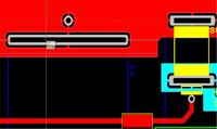
I have developed a board in Easy-PC 14 involving slots, but when I exported the data to Gerber and looked at in GC-Preview, I discovered that the rectangular holes I placed in my slots have been rendered as round holes.

Is this likely to be a display issue in GCPreview, or do I have a genuine issue where the board will be manufactured incorrectly?

I have attached 2 images showing the original data out of the CAD and what I have seen on the GCPreview plot.

thanks
--dave


I don't know how you define a "rectangular" hole in Easy-PC, but it needs to be milled by the PCB Fab anyway, and defining a "throughplated" milling contour as a separate gerber layer is most likely the best way. Alternatively, you can inform the Fab, that a particular unique drill diameter is marking a slot cutout. In any case, you should ask them in advance about their requirements for throughplated slots. The option is most likely not provided for pool fabrication of PCBs.
 
Problem solved:

If the hole in the slot is defined as a rounded rectangle, the minimum router size needs to be impractically small. This was solved by using an oval hole, requiring a router cutter the width of the slot.

Thanks for your advise FvM, I'll be accompanying my data with a phonecall to ensure that they can fulfill what i want to do. When I checked my modified holes on GCPreview, they were shown in the routing table with start and end locations and the correct slot diameter cutter.

--dave
 

It depends who you use for PCB manufacture, but PCB-Pool have no problems routing slots in prototype boards. It is worthwhile telling them just in case you have used a non-standard layer for the information which could result in it being missed.

Keith.
 

give special insruction to the PCB fabricator to cut slot in required area . normally what I follow is there will be a gerber layer which includes some notes for the fabricator ( say drill chart, tolerance etc) .I will add some notes regarding this slot in the drill chart. (cadence ALLEGRO drill chart automatically generate information for slot). see the attached picture.

Normally your ncdrill file contain information about round holes only.(you can open this file using a text editor)
so you can not blame GCprevue for this issue .
 

Normally your ncdrill file contain information about round holes only.(you can open this file using a text editor)
so you can not blame GCprevue for this issue .
https://obrazki.elektroda.pl/8_1288754029.jpg

Thats interesting about no slot information in the NCDrill file, I didn't know that.

I wasn't actually blaming GCPreview for this issue, I subsequently discovered that the information is being incorrectly exported from the CAD package

--dave
 

AFAIK all slots will be created with either a chain drill or a routing bit and so will not actually have rounded corners.
If you want a square corner then the board has to be punched - which is not something that gets output in gerbers so needs adding to
your drilling drawing for special attention for the fab house (and can cost extra).
 

Status
Not open for further replies.

Part and Inventory Search

Welcome to EDABoard.com

Sponsor

Back
Top