oliglaser
Junior Member level 3

- Joined
- Feb 26, 2010
- Messages
- 31
- Helped
- 0
- Reputation
- 0
- Reaction score
- 0
- Trophy points
- 1,286
- Location
- Manchester, UK
- Activity points
- 1,688
Hi all,
Specs and Goals
Input Voltage ~20V DC/AC coupled
Input Impedance = 1 megaohm
Supply Voltage = +5V
ADC range = 1.5 to 3.5V
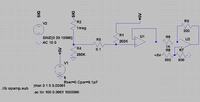
I am trying to design an oscilloscope input using a single supply opamp (+5v) so I need to shift the input common mode voltage to 2.5V while dividing it by 10. I have no problems doing this either with inverted or non-inverted design, but keeping the input impedance at 1 Megaohm for DC-20MHz is not as easy - if I use a reference voltage then the AC sees a lower impedance with a non inverting setup, and if I use an inverting setup then the impedance changes with the input voltage due to the voltage shifting. Can anybody advise me on this? Do I have to compromise or is there a better way to proceed?
Any help would be most appreciated.


