Continue to Site

Welcome to EDAboard.com

Welcome to our site! EDAboard.com is an international Electronics Discussion Forum focused on EDA software, circuits, schematics, books, theory, papers, asic, pld, 8051, DSP, Network, RF, Analog Design, PCB, Service Manuals... and a whole lot more! To participate you need to register. Registration is free. Click here to register now.

Single Gate drive transformer for Two Tran Forward?

cupoftea

Advanced Member level 6
Joined
Jun 13, 2021
Messages
3,050
Helped
62
Reputation
124
Reaction score
139
Trophy points
63
Activity points
15,937
Hi,
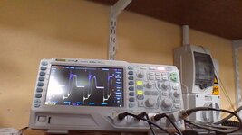
As you can see, the single GDT in the hi side means top fet takes all the switch on loss (most of it), bottom one takes most of the turn off loss.
So whats wrong with this..why do the purists hate it?
Why do all use GDT in hi and low side?
(Yellow is upper fet vds...other is lower fet vds)

The lower fet is directly driven here...no GDT
Upper fet is driven by GDT.

Its 130W, 120kHz, 24vout, 180vac input
 

Attachments

  • VDS _yellow is upper.jpg
    VDS _yellow is upper.jpg
    188.9 KB · Views: 85
Last edited:
On the other hand, what about this opposite approach? ie, both FETs being driven off the same gate drive transformer..

Opposite Approach.....
We will do a Gate drive transformer (GDT) for a Offline Two Transistor Forward.
We will have both FETs driven from a secondary coming from this same GDT.
We will use EFD20107 with 3F3 ferrite, and no gap.
Primary will be two series halves, each of 36 turns.
These will "sandwich" the two secondaries.
We will make secondary1 of 72 turns, (2 layers of 36 turns)
Ditto secondary two.
I believe that this "double layer" secondary thing will mean less
interwinding capacitance from pri to sec.
Would you agree?
pri, sec1 and sec2 will each be 6.2mH.

I mean, you can scope the top gate drive out by just scoping the identical bottom one.
And in theory, both FETs have more chance of having the same switching loss?
 
As you can see, the single GDT in the hi side means top fet takes all the switch on loss
I don't see due to missing waveform trace annotation. Is it asking too much to expect a screenshot dump from Rigol oscilloscope instead of a photo?
 

LaTeX Commands Quick-Menu:

Similar threads

Part and Inventory Search

Welcome to EDABoard.com

Sponsor

Back
Top