JimPierce
Newbie level 5

- Joined
- Aug 14, 2012
- Messages
- 8
- Helped
- 0
- Reputation
- 0
- Reaction score
- 0
- Trophy points
- 1,281
- Activity points
- 1,360
Hi,
I need to connect a signal source to a DAQ device and I have some questions with regards to the basics of using single-ended/pseudo-differential connections.
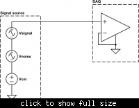
- I have a signal source that has a small DC offset (Vcm) relative to circuit ground for the DAQ device. There's also a small AC common mode component (Vnoise) which could represent noise coupled into the wires connecting the signal source to the DAQ.
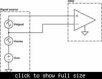
- The first diagram I have attached shows how I would connect the signal source to the DAQ using a single-ended connection. Second diagram shows how I would make a pseudo-differential connection.
Questions:
1. It's clear to me that in the case of the single-ended connection, the DAQ will measure the sum of Vsignal, Vcm and Vnoise - the signal will be indistinguishable from the noise and offset. As I understand it, this shouldn't be the case when using the pseudo-differential connection (the DAQ should measure Vsignal only), although I've read several places that pseudo-differential connections only reject common mode signals which are DC:
**broken link removed**
Why won't it reject the AC common mode component aswell? As far as I understand, the DAQ should just measure the voltage difference and any common mode component will be rejected, be it AC or DC.
2. In the case of the single-ended connection, if I only route a single wire between the signal source and DAQ device, and route no return wire close to the signal wire, won't I make a potentially huge loop for magnetic flux to penetrate and couple noise into? Should I always route a return wire, even though it's a single-ended connection, close to the signal wire and connect it to the DAQ ground? I know this will create a ground loop, my question more relates to the necessity of a return wire.
Any help will be greatly appreciated!
Thank you.
Edit:
I understand a pseudo-differential connection to be where you connect the reference of a signal source to the negative terminal of the DAQ and the signal to the postive, or the other way around depending on the polarity you want. I assume a fully differential connection would be where you, at the signal source, convert the signal to the difference between two signals 180 deg out of phase and transmit them using two wires to the DAQ inputs. I just don't understand why this is better than the pseudo-differential case.


Last edited:
