Continue to Site

Welcome to EDAboard.com

Welcome to our site! EDAboard.com is an international Electronics Discussion Forum focused on EDA software, circuits, schematics, books, theory, papers, asic, pld, 8051, DSP, Network, RF, Analog Design, PCB, Service Manuals... and a whole lot more! To participate you need to register. Registration is free. Click here to register now.

single ended to "differential" line driver

Status
Not open for further replies.

simonak

Newbie level 6
Newbie level 6
Joined
Nov 22, 2015
Messages
12
Helped
0
Reputation
0
Reaction score
0
Trophy points
1
Activity points
101
hello,
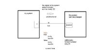
I need help in finding an ic or designing a circuit
that will convert and drive single ended to differential line (digital)

but the differential logic levels is different than the normal:

true: hi: 5v
lo:0v

false: hi: 0v
lo: 0v

thank you
 

but the differential logic levels is different than the normal:

true: hi: 5v
lo:0v

false: hi: 0v
lo: 0v
What's differential here? Tying one line to ground makes single ended signaling.
 
I thought about it but don't want to do so
because this line is going out from the pcb
and I don't want to create ground loop ,the line length could be a few meters and the environment is noisy.
so I would like to separate the ground from the output.
 

Isolated ground is not the same as differential.
It seems you are looking for something completely isolated since there is no point in isolating the ground but not the signal line. Consider optical isolation or true differential which uses two wires but the logic is:
wire A = the input signal
wire B = the inverted input signal

You still have to keep both the differential wires within the allowed input voltage range of the differential receiver.

Brian.
 
How about doing an impedance balanced line, this implies making the impedance to ground equal at the sending end, maybe 50 or 100 ohms in series with each leg, with one leg biased up a couple of volts to give a clear threshold?

You only drive one leg, and at the receiver you use something like a RS485 receiver chip to covert to singled ended referenced to the local ground, you must still meet the common mode range limits at the receiver obviously, and you get about 6dB less noise margin then you would with a differential drive setup, but it is still orders of magnitude better then an unbalanced line.

But seriously, if the link is slow use an opto, if fast use 8b10 or Manchester coding and a transformer....

Regards, Dan.
 
You can't "separate the ground" without isolating the output driver or increasing the common mode impedance somehow.

Some additional information is necessary: type of cable, connection at the peer, single ended or differential receiver, uni- or bidirectional communication?
 

Isolated ground is not the same as differential.
It seems you are looking for something completely isolated since there is no point in isolating the ground but not the signal line. Consider optical isolation or true differential which uses two wires but the logic is:
wire A = the input signal
wire B = the inverted input signal

You still have to keep both the differential wires within the allowed input voltage range of the differential receiver.

Brian.

I can't use either because I will need to use two separate supplies
and I can't modify the device I'm connected to.

You can't "separate the ground" without isolating the output driver or increasing the common mode impedance somehow.

Some additional information is necessary: type of cable, connection at the peer, single ended or differential receiver, uni- or bidirectional communication?

the cable is twisted pair
the receiver is differential
unidirectional

How about doing an impedance balanced line, this implies making the impedance to ground equal at the sending end, maybe 50 or 100 ohms in series with each leg, with one leg biased up a couple of volts to give a clear threshold?

You only drive one leg, and at the receiver you use something like a RS485 receiver chip to covert to singled ended referenced to the local ground, you must still meet the common mode range limits at the receiver obviously, and you get about 6dB less noise margin then you would with a differential drive setup, but it is still orders of magnitude better then an unbalanced line.

But seriously, if the link is slow use an opto, if fast use 8b10 or Manchester coding and a transformer....

Regards, Dan.

I can't modify the device I'm connected to or the line.
the signal is system BIT that goes true when the system is functional
 
Last edited by a moderator:

the cable is twisted pair
the receiver is differential
unidirectional
O.K., why not using a true differential driver, e.g. a RS422/485 driver IC?

Operating the connection in a pseudo differential manner (single-ended driver, differential receiver) gives some common mode rejection, too.
 

O.K., why not using a true differential driver, e.g. a RS422/485 driver IC?

Operating the connection in a pseudo differential manner (single-ended driver, differential receiver) gives some common mode rejection, too.

but the logic levels of those drivers are +-5v:
true:
hi: 5v
lo: 0v
false:
hi: 0v
lo: 5v
 

Yes, what's wrong with it if the receiver is differential?

my mistake
by differential I mean that the input is two lines
that the "low" line is the reference for the "hi" line.
but the logic levels are as I described at the begining (like single ended).
 

I can't use either because I will need to use two separate supplies
The levels are NOT +5V/-5V they are still 0V and +5V but the logic state of one wire relative to the other wire is opposite.
To be honest, I can't see any point in using twisted pairs if the signal isn't differential. Twisting a single ended link actually makes the SNR worse!

Brian.
 

The levels are NOT +5V/-5V they are still 0V and +5V but the logic state of one wire relative to the other wire is opposite.
To be honest, I can't see any point in using twisted pairs if the signal isn't differential. Twisting a single ended link actually makes the SNR worse!

Brian.
I know
I mean that with optocoupler you need separate supplies one of the pcb and one of the receiver. The receiver needs to pull up the hi line and connect the lo line to the receiver's gnd.
and I can't alter the receiver.
 

Differential receiver? Opto coupler? Increasing confusion.

How about sketching the actual receiver circuit?
 

Hi,

RS485 and RS485 both need two twisted signal wired AND a GND connection.
The common mode input range usually is +/- 7V, even if supplied with single 5V.

About the signal levels.
The drivers usually are supplied with single +5V.
So if you measure each signal line referenced to GND you see levels of 0V and 5V.
But if you measure the same signals differentially you see +5V and -5V.

( Fore sure not exactely 5.0V, rather 3V when terminated with 120Ohms. But the receiver needs only 200mV of difference)

Klaus


because regular differntial driver outputs is:
true:
hi: 5v
lo: 0v
false:
hi: 0v
lo: 5v
and the receiver lo line should always be 0v
 

Re: single ended to "differential" line driver

You didn't answer the question about the receiver circuit and why it can't be driven by regular differential driver.

- - - Updated - - -

If you don't know the actual receiver circuit, can you give at least a complete specification, absolute and differential voltage range of "hi" and "lo" line, receiver threshold level?
 

I agree the logic levels are confusing, it seems 'true' can be the same level as 'false' so I'm not sure how to tell them apart.

I would still go for an optical solution but do it like this:

At the 'my system' end, use the status signal to drive the LED side of an opto-coupler.
ALSO AT THE 'my system' END - wire an isolated 5V supply (suggest an NME0505 or similar DC-DC converter). Use it to provide pull-up current of about 5mA and nothing else, do not connect it to the system ground. Then use the output side of the opto-coupler as your signal to the other system. It gives you a completely isolated TTL level signal without having to do any modification to the receiving end.

Brian.
 
Status
Not open for further replies.

Part and Inventory Search

Welcome to EDABoard.com

Sponsor

Back
Top