Continue to Site

Welcome to EDAboard.com

Welcome to our site! EDAboard.com is an international Electronics Discussion Forum focused on EDA software, circuits, schematics, books, theory, papers, asic, pld, 8051, DSP, Network, RF, Analog Design, PCB, Service Manuals... and a whole lot more! To participate you need to register. Registration is free. Click here to register now.

Sine Look Up Table Clarification

Status
Not open for further replies.

electronicsman

Full Member level 5
Full Member level 5
Joined
May 4, 2012
Messages
291
Helped
11
Reputation
22
Reaction score
12
Trophy points
1,298
Activity points
3,737
I am planning to understand the sine look up table. Let us say i create a 64 element sine look up table. Hence the calculations are like 2*Pi/64 increments.
Now suppose i have to access the elements with the table index pointer. If i use the 48KHz sampling frequency the table index i get is different and if i use the 20KHz sampling frequency i get a different table index. For 48KHz sampling frequency of 2KHz sine wave it is (2k* 64 )/(48K) = 2.66. For 20KHz it is (2k * 64) / 20K = 6.4. I have attached the calculations. My doubt is which one is correct? Does both represent 2KHz sine wave? One more doubt is for float values like 2.66 which integer value shall i take 2 or 3. Does it not affect the accuracy? Please help.
 

Attachments

  • Test.pdf
    24.5 KB · Views: 246

electronicsman, I think you misunderstand how the table is used to generate different frequencies. You don't normally use a different set of values for each frequency or sampling rate you use. Your table is essentially the points of a sine wave (or part of a sine cycle) scaled according to the way you want to use it. The figures are fixed for all frequencies and sampling rates, the way you produce different output frequencies is you read the table (advance your index pointer) at different rates. Thus the wave shape stays the same but the speed at which you reconstruct it changes.

I'm not sure what your final application is but making float numbers into integers will introduce considerable distortion. A better method if you need an integer result is to scale the table values so they fall between the minimum and maximum values you need to use. For example, if you want an 8-bit result and no negative values, you multiply the sine value by a number by 127 and add 128 to the result. That makes sine values range between 1 and 255 with minimal distortion and no negative values.

Brian.
 

Yes i think i am doing the same if it is a 64 value table i am storing in a array table of 64 sine values. Based on frequency my table index i am calculating. Please confirm me my calculations correct or not
For 2KHz sine wave the index is 2k * 64/48k for a 48k sampling for 3k sine it is 3k* 64/48k. Am i correct? Suppose if it is 20k sampling it is 2k*64/20k. I am confused.
 

What exactly are you trying to do?

If your 'sampling' is the speed you read the table, you only have 2.66 entries in it and you get almost a square wave result. Are you trying to store ONLY 2KHz and 3KHz signals with a fixed sampling rate or do you want to store other frequencies as well?

There is no point in the index ever being bigger than the table, all it does is look up one of the 64 values so it's range will be 1 to 64 (or 0 to 63), there is no calculation involved.

Brian.
 

No not only 2khz the frequency is a variable based on that i calculate the table index.
 

Hi,

Sadly you give only vague informations.
It shouldn't be too difficult (or is it some kind of secret?) to specify the range of output frequency.

Additionally it's not clear to me how your software works... how it generates the output values.
I even don't know how many columns your table in your software has. Float or integer...

Klaus
 

No not only 2khz the frequency is a variable based on that i calculate the table index.
Sorry but that doesn't make sense. The table index points to one of the 64 entries in the sine table, to recreate the sine shape it has to read all the 64 values. It doesn't matter what the frequency is, the index range should always be the same. If you limit it to less than 64 you reduce the quality of the sine shape and if you use more than 64 you 'fall off' the end of the table.

Brian.
 

I am sorry nothing like secret, i am referring to the micro chip application note AN1017A where i was trying to analyze the look up table. It is very difficult for me to think from your point of view and do not know how much
and what information to be given.
 

Hi,

We don't know what frequencies or what frequency range you want to generate.
We don't know how you or your software tries to do this.

This makes helping difficult.

Klaus
 

Frankly speaking when you said that then i started thinking of the frequency range because my assumption was i can represent all the frequencies using the 64 table sine table. Here is the code i am referring to
Code:
void __attribute__((interrupt, no_auto_psv)) _T1Interrupt (void)
{
	IFS0bits.T1IF = 0;
	Period = ActualCapture - PastCapture;  // This is an UNsigned substraction
                                           // to get the Period between one 
                                           // hall effect sensor transition

    // These operations limit the Period value to a range from 60 to 6000 rpm
[B]	if (Period < (unsigned int)MINPERIOD)  // MINPERIOD or 6000 rpm
		Period = MINPERIOD;
	else if (Period > (unsigned int)MAXPERIOD) // MAXPERIOD or 60 rpm
		Period = MAXPERIOD;

    // PhaseInc is a value added to the Phase variable to generate the sine
    // voltages. 1 electrical degree corresponds to a PhaseInc value of 184,
    // since the pointer to the sine table is a 16bit value, where 360 Elec
    // Degrees represents 65535 in the pointer. 
    // __builtin_divud(Long Value, Int Value) is a function of the compiler
    // to do Long over Integer divisions.
	PhaseInc = __builtin_divud(512000UL, Period);	// Phase increment is used
								 					// by the PWM isr (SVM)
[/B]
    // This subroutine in assembly calculates the MeasuredSpeed using 
    // fractional division. These operations in assembly perform the following
    // formula:
    //                   MINPERIOD (in fractional) 
    //  MeasuredSpeed = ---------------------------
    //                    Period (in fractional)
    //

	__asm__ volatile("repeat #17\n\t"
                     "divf %1,%2\n\t"
                     "mov w0,%0" : /* output */ "=g"(MeasuredSpeed)  
                                 : /* input */ "r"(_MINPERIOD),
                                               "e"(Period)
                                 : /* clobber */ "w0");

    // MeasuredSpeed sign adjustment based on current motor direction of 
    // rotation
	if (Current_Direction == CCW)
		MeasuredSpeed = -MeasuredSpeed;

    // The following values represent the MeasuredSpeed values from the 
    // previous operations:
    //
	// CONDITION        RPM          SFRAC16      SINT      HEX
	// Max Speed CW  -> 6000 RPM  -> 0.996805  -> 32663  -> 0x7F97
	// Min Speed CW  -> 60 RPM    -> 0.009984  -> 327    -> 0x0147
	// Min Speed CCW -> -60 RPM   -> -0.009984 -> -327   -> 0xFEB9
	// Max Speed CCW -> -6000 RPM -> -0.996805 -> -32663 -> 0x8069

	SpeedControl(); // Speed PID controller is called here. It will use 
                    // MeasuredSpeed, RefSpeed, some buffers and will generate
                    // the new ControlOutput, which represents a new amplitude
                    // of the sinewave that will be generated by the SVM 
                    // subroutine.

#ifdef PHASE_ADVANCE
	// Calculate Phase Advance Based on Actual Speed and MAX_PH_ADV define
        // The following assembly instruction perform the following formula
        // using fractional multiplication:
        // 
        // PhaseAdvance = MAX_PH_ADV * MeasuredSpeed
        //

        register int a_reg asm("A");
        a_reg = __builtin_mpy(_MAX_PH_ADV, MeasuredSpeed, 0,0,0,0,0,0);
        PhaseAdvance = __builtin_sac(a_reg,0);
           
#endif

	MotorStalledCounter++;	// We increment a timeout variable to see if the
                            // motor is too slow (not generating hall effect
                            // sensors interrupts frequently enough) or if
                            // the motor is stalled. This variable is cleared
                            // in halls ISRs
    if ((MotorStalledCounter % _10MILLISEC) == 0)
	{
		ForceCommutation();	// Force Commutation if no hall sensor changes 
                            // have occured in specified timeout.
	}
	else if (MotorStalledCounter >= _100MILLISEC)
	{
		StopMotor(); // Stop motor is no hall changes have occured in 
                     // specified timeout
	}
	return;
}

I have attached the source code. I am implementing the same code trying to customize for my requirements and the rpm initially trying 6000.
 

Attachments

  • AN1017_30F3010_V1.zip
    77.5 KB · Views: 143

Unfortunately Microchip have slightly confused the code by giving a table covering 60 degrees in decimal numbers but given the offsets for +60, +120, +180, +240 and +300 degrees in hexadecimal. It isn't incorrect but for those of us without 16 fingers it makes the calculation a bit harder.

It does as I said before though, the table stays as it is, regardless of the frequency. It's the rate at which the values are read from it that decides the output frequency.

Brian.
 

Sorry to ask it here but i have one clarification from this link https://www.microchip.com/forums/m421226.aspx
about the #define PHASE_ZERO 57344
For that the response is "That is -45 degrees. It depends on position of sensors relative to stator in electrical degrees. Find angle in your setup." Can someone please help me how did he get it? I am trying hard to get the answer but unable to get it.
 

You may consider the following:

It may be more convenient to use integer arithmetic (then the table will be all positive numbers (say 0-1023 or something like that). That means your table contains 511*(sin(t)+1). with t going from 2*pi*t/64 to 2*pi*t*63/64

We know that it is sufficient to store 1/2 the points and you can get better resolution that way- just alternate the result with +/-1. It is not difficult.

You just need only one table and you can generate any frequency just by manipulating the timer interrupts.
 

You have correctly stated the formula for the increment.

incr = fout * 64 / fsamp

Note that you cannot produce frequencies greater than 1/2 the sampling frequency, and frequencies close to this will be highly distorted. At 1/2 the sampling frequency, you will be accessing only 2 elements in the table, and the output will be highly dependent on where it starts in the table.

You must use the full fractional value for the increment. You can use a float or fixed point notation for it, but simply truncating the number to an integer does not work. For example, lets try to see what the increment is for 500Hz.

incr = 500 * 64 / 48000 = 0.667

So, for your 500 Hz output you index proceeds like this:

0.0
0.667
1.334
2.001
2.668
3.335
4.002
4.669

So you round these to integers to actually index the table and you get:

0,
1,
1,
2,
3,
3,
4,
5

Hope this helps.

Bob
 
Last edited:
Thank you for the reply. My doubt is what is the method to be followed to arrive at PHASE_ZERO because in one of micro chip project he is using 0 and the other it is 57344? Please advise.
 

My doubt is what is the method to be followed to arrive at PHASE_ZERO because in one of micro chip project he is using 0 and the other it is 57344?

The math behind the duty cycle calculation is that...

Code:
2^16 - 2^13 = 57344
360 - 360/8 = 360 - 45 = 0 - 45 = -45

You can advance the phase by 45 degrees by building the sinewave starting at the end of the 'previous' wave.
 

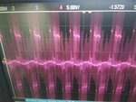
I was trying with the application note AN1017A sinusoidal control. I am able to run the motor it seems to run smoothly and seem to draw less current. Please find the wave forms of phase voltage R with respect to Y. Can you confirm it is ok or i need to fine tune further. I am not sure which is the exact waveform to get. Can you provide reference waveform?
 

Attachments

  • Sinusoidal.jpg
    Sinusoidal.jpg
    101.9 KB · Views: 182

Impossible to recognize anything. You either need to low pass filter the motor voltage or measure motor current with a suitable probe.
 

This is the best i could do for current waveform through current probe. If not better i can try once again. Please provide your feedback.
 

Attachments

  • IMG_20180502_184912.jpg
    IMG_20180502_184912.jpg
    512 KB · Views: 164

Status
Not open for further replies.

Similar threads

Part and Inventory Search

Welcome to EDABoard.com

Sponsor

Back
Top