FreshmanNewbie
Advanced Member level 1

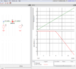
Below I have this simulation.
The diodes represent the clamping diodes placed inside the microcontroller GPIO pins.
Case 1 - Given directly using the voltage source.

Case 2 - Given the same voltage through a resistor divider.

In the above image, both the circuits are providing 12V at the GPIO pin. But first one is given through the voltage source. Second is through a resistor divider network. But effectively, same voltage is given and provide at the GPIO pin. But we are getting different results.
I understand that in the first case, since the Voltage source output is very low impedance, it is showing 12V. But I am confused on this behaviour and unable to arrive at a conclusion on how the 2 cases are different. Please help to provide an answer in simple terms for my clarity.
The diodes represent the clamping diodes placed inside the microcontroller GPIO pins.
Case 1 - Given directly using the voltage source.
Case 2 - Given the same voltage through a resistor divider.
In the above image, both the circuits are providing 12V at the GPIO pin. But first one is given through the voltage source. Second is through a resistor divider network. But effectively, same voltage is given and provide at the GPIO pin. But we are getting different results.
I understand that in the first case, since the Voltage source output is very low impedance, it is showing 12V. But I am confused on this behaviour and unable to arrive at a conclusion on how the 2 cases are different. Please help to provide an answer in simple terms for my clarity.