anushaas
Member level 5

- Joined
- Jan 4, 2011
- Messages
- 84
- Helped
- 0
- Reputation
- 0
- Reaction score
- 0
- Trophy points
- 1,286
- Activity points
- 1,979
Hi
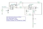
The following circuit was simulated using Tina 9 and the hardware implementation for the same was done on an NI Elvis II+ board

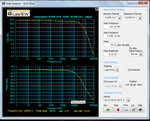
The frequency response of the circuit with load resistance R6 as 10k on simulation gave a -3dB gain at 7.8MHz as shown below

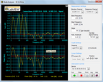
However the same on implementation gave a -3dB gain at 630.957kHz approx.The response obtained is as shown below

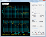
The response (simulation and hardware) for R6 as 10Ohm is as shown below:


I understand that practical implementation will involve parasitic capacitances in the circuit but will the variation be this much?
The following circuit was simulated using Tina 9 and the hardware implementation for the same was done on an NI Elvis II+ board

The frequency response of the circuit with load resistance R6 as 10k on simulation gave a -3dB gain at 7.8MHz as shown below

However the same on implementation gave a -3dB gain at 630.957kHz approx.The response obtained is as shown below

The response (simulation and hardware) for R6 as 10Ohm is as shown below:


I understand that practical implementation will involve parasitic capacitances in the circuit but will the variation be this much?


