Continue to Site

Welcome to EDAboard.com

Welcome to our site! EDAboard.com is an international Electronics Discussion Forum focused on EDA software, circuits, schematics, books, theory, papers, asic, pld, 8051, DSP, Network, RF, Analog Design, PCB, Service Manuals... and a whole lot more! To participate you need to register. Registration is free. Click here to register now.

Simple variable AF oscillator produces square instead of sine

Status
Not open for further replies.

neazoi

Advanced Member level 6
Joined
Jan 5, 2008
Messages
4,134
Helped
13
Reputation
26
Reaction score
15
Trophy points
1,318
Location
Greece
Activity points
37,023
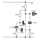
Hi this oscillator can be tuned from less than 1khz to more than 3khz by replacing the 10k resistors with a stereo potentiometer.
However, this circuit produces a square wave. I thought it was a phase shift RC oscillator which should produce a sine wave.
What may be the problem?
 

Attachments

  • gatesn.gif
    gatesn.gif
    3.8 KB · Views: 164

i'm not familiar with this circuit. however, the information I found on the internet:

https://www.electronics-tutorials.ws/oscillator/rc_oscillator.html

indicates that your 560k resistor should be tied to the supply not the collector,
and that instead of an output capacitor, there is an output resistor

there is also a 10k resistor from base to ground missing, so the phase shift from output (collector) to input (base) is 120 degrees not 180 degrees
 

Install a 10k resistor from ground to the transistor bias. This phase shift oscillator is not always easy to get started. The righthand 6.8nF capacitor needs to discharge exactly as much as it charges through each cycle. Therefore bias current needs to be adjusted precisely, so it biases the transistor in the proper range of operation to produce sine waves.

If you experiment at varying one resistor (I'm not sure which one), you might manage to find an easy way to change frequency, rather than by varying two resistors.

- - - Updated - - -

In addition, to make it easier to get oscillations going, consider making 4 RC stages. Then each stage only needs to have 45 degrees phase shift, adding up to overall 180 degrees.

On second thought, it is unlikely that we can easily vary frequency by altering only one component. However another sidnewave oscillator, namely the twin-T, does let you vary frequency via a single resistor adjust.
 
  • Like
Reactions: neazoi

    neazoi

    Points: 2
    Helpful Answer Positive Rating
In twin-T or a phase shift oscillator the purity of the waveform depends on equal phase shift in each RC section. Changing only one resistance will pull the frequency but at the expense of wave shape. In twin-T, there should always be a 1:2 relationship between capacitor and resistor values, in a phase shift oscillator the sections should have equal values. The easiest tuneable AF sine source using only twin gang resistors is probably a Wien-bridge oscillator but it requires more than one stage of gain.

Brian.

Sometimes it seems difficult to do simple things. Is there any topology that could be used to make a simple discrete variable AF oscillator? I am interested in 1KHz to 2.5KHz. I do not want to use thermistors or incandescent bulbs.
 

Thermistors and incandescent lamps were used to stabilize the amplitude in prehistoric times. I did a quick search for useful schematics and probably the simplest is at:
https://www.learnabout-electronics.org/Oscillators/osc34.php
near the bottom of the page. It uses a cheap op-amp, if you substitute a more modern type it will give even better results. Note it only needs a dual gang potentiometer and there is a useful hint on the page on how to ensure the two pots are well matched.

Brian.
 
  • Like
Reactions: neazoi

    neazoi

    Points: 2
    Helpful Answer Positive Rating
Status
Not open for further replies.

Similar threads

Part and Inventory Search

Welcome to EDABoard.com

Sponsor

Back
Top