B
BlackMamba
Guest


Source: Jak z TV zrobić prosty oscyloskop
Project by cosimo
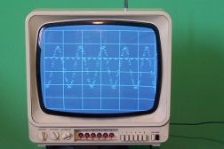
Device is very simple and consists of two integrated circuits.
Parameters:
Time base ranges:
0,1ms/div
0,2ms/div
1ms/div
2ms/div
4ms/div
8ms/div
16ms/div
Input sensitivity 0,2V/div (May be changed with R14)
Displaying:
-run 90x120 pix (approximately)
- software generated scale (intensity may be adjusted changing R8)
- RMS signal level (dashed line)
- trigger level cursor (dash AT righ side of screen)
- LEDs indicate current time base range
Controls:
- x advance – controlled by potentiometer
- y advance – controlled by potentiometer
- trigger level – controlled by potentiometer
Due to input circuit device soul have Power supply galvanically separatek from sources of signals being measured!!!