wfg42438
Member level 3

- Joined
- Jun 29, 2015
- Messages
- 54
- Helped
- 0
- Reputation
- 0
- Reaction score
- 0
- Trophy points
- 6
- Location
- California
- Activity points
- 620
Hello I am attempting to set up three cascaded counters each going to BCD decoders and then to seven segment displays. i have one low frequency clock being applied to the clock up signal which i am attempting to count. An additional clock is also being used for the reset line of all counters. Please note that the input clock is a low frequency signal of approximately 1-35 Hz, and i wish to have the other clock reset the counter every 28.8 seconds so this clock has a frequency of 34.72mhz.
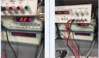
Please note that for now the clock signals have been given logic high levels of 5V and a logic low of 0V
You might be wondering why i want to set up such a slow and odd counter well this is for a project iam working on which is well described in this thread: https://www.edaboard.com/threads/353222/#post1512642
A much better solution has already been proposed but i am really curios to see how this counter works before i attempt the proper solution in the thread above.
Now for the counters i wish to use the count up function therefore i have held Enable, and count down high by applying VDD (5V) as specified in the data sheet
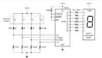
For the decoders i was not too sure about the connection scheme so i looked over an old digital logic lab book and saw the connection scheme attached. Please note i have used the 330 ohm resistors at the output of the decoder and the 1k resistor with one end to VDD and the other tied to LT, BI/RBO & RBI
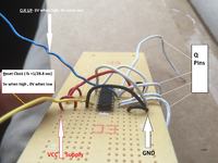
Attached is also a sketch of the connections i have made for the counter please note that this sketch shows the connections for a single set of counter and decoders . I have also shown a connection scheme for the cascaded counters in an additional image


As of now i have built and tested the circuit however the counters don't seem to work properly, when checking them i don't see it counting when probing the Q outputs using an oscilloscope, i only see noise.
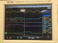
I then built a single counter and decoder to see if maybe something was connected improperly and here i periodically saw a count when using the scope however it was not very clean (Image attached) . Even then the however the decoders did not output anything. When probing the a-g pins on the decoder with a voltmeter i saw the decoder was sending nothing to the 7 segment displays as the voltmeter always read 0V across those pins

Please let me know if any of the connections shown are incorrect i would really appreciate the feedback! I am sure there is something i am forgetting to do which is why the set up is giving me nothing, thank you in advance!
Link to Data Sheets:
https://www.mouser.com/ds/2/405/cd4511b-452627.pdf
https://www.mouser.com/ds/2/405/cd40192b-439702.pdf
Please note that for now the clock signals have been given logic high levels of 5V and a logic low of 0V
You might be wondering why i want to set up such a slow and odd counter well this is for a project iam working on which is well described in this thread: https://www.edaboard.com/threads/353222/#post1512642
A much better solution has already been proposed but i am really curios to see how this counter works before i attempt the proper solution in the thread above.
Now for the counters i wish to use the count up function therefore i have held Enable, and count down high by applying VDD (5V) as specified in the data sheet
For the decoders i was not too sure about the connection scheme so i looked over an old digital logic lab book and saw the connection scheme attached. Please note i have used the 330 ohm resistors at the output of the decoder and the 1k resistor with one end to VDD and the other tied to LT, BI/RBO & RBI
Attached is also a sketch of the connections i have made for the counter please note that this sketch shows the connections for a single set of counter and decoders . I have also shown a connection scheme for the cascaded counters in an additional image


As of now i have built and tested the circuit however the counters don't seem to work properly, when checking them i don't see it counting when probing the Q outputs using an oscilloscope, i only see noise.
I then built a single counter and decoder to see if maybe something was connected improperly and here i periodically saw a count when using the scope however it was not very clean (Image attached) . Even then the however the decoders did not output anything. When probing the a-g pins on the decoder with a voltmeter i saw the decoder was sending nothing to the 7 segment displays as the voltmeter always read 0V across those pins

Please let me know if any of the connections shown are incorrect i would really appreciate the feedback! I am sure there is something i am forgetting to do which is why the set up is giving me nothing, thank you in advance!
Link to Data Sheets:
https://www.mouser.com/ds/2/405/cd4511b-452627.pdf
https://www.mouser.com/ds/2/405/cd40192b-439702.pdf


